Introduction
Precise timing forms the backbone of many electronic projects, from simple clocks to microcontroller-based gadgets. A DIY crystal oscillator provides hobbyists with a reliable way to generate stable frequencies without relying on pre-built modules. Building your own crystal oscillator circuit allows you to customize frequency and understand the underlying principles firsthand. This crystal oscillator tutorial guides you through the process, starting from basic concepts to practical assembly. Whether you are prototyping on a breadboard or designing a PCB, these circuits deliver accuracy essential for timing-sensitive applications. Hands-on construction sharpens skills in component selection and troubleshooting.
What Is a Crystal Oscillator and Why Build Your Own?
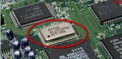
A crystal oscillator uses a quartz crystal to produce a highly stable sinusoidal output at a specific frequency. Quartz crystals exhibit the piezoelectric effect, converting electrical energy into mechanical vibrations and vice versa. This results in frequencies with minimal drift, far superior to RC or LC oscillators for precision tasks. In hobbyist projects, crystal oscillators drive microcontrollers, generate clock signals, or serve as reference sources for radios.
Building your own offers control over parameters like frequency and load capacitance, tailored to your needs. Commercial units work well but limit experimentation and can be costly for multiples. A DIY approach teaches circuit behavior, such as startup time and phase noise. It also integrates easily into custom PCBs for compact designs. For electronic hobbyists, this hands-on method builds confidence in tackling more complex timing circuits.
Technical Principles of Crystal Oscillators
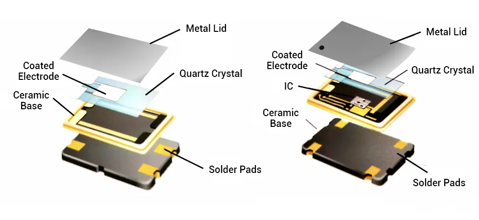
Quartz crystals resonate at precise frequencies determined by their physical cut and thickness. They operate in series or parallel modes, with parallel mode common in oscillators due to higher impedance. The crystal presents a narrow bandwidth around its resonant frequency, ensuring stable oscillation when paired with an amplifier. Feedback from the amplifier sustains vibrations, while load capacitors define the exact operating point.
The Pierce oscillator topology suits DIY crystal oscillators, using a single inverter stage for amplification. It includes a feedback resistor and two load capacitors forming a pi-network with the crystal. Oscillation occurs when loop gain exceeds unity and phase shift is 360 degrees. Startup relies on noise amplification until the crystal locks in. Temperature affects frequency slightly via the turnover point, but AT-cut crystals minimize this for hobbyist use.
Colpitts configurations offer alternatives with transistors, splitting capacitance for feedback. Both topologies demand careful component matching to avoid parasitic effects. Understanding these principles prevents common pitfalls like failure to oscillate.
Essential Crystal Oscillator Components
Core crystal oscillator components include a quartz crystal, typically 1 MHz to 20 MHz for DIY projects. Load capacitors, around 18 pF to 33 pF each, match the crystal's specified load capacitance. A feedback resistor of 1 MOhm provides DC bias and negative resistance. An inverter IC, such as from the 74HC series, acts as the amplifier with low power draw.
Series resistors, 0 to 1 kOhm, limit drive level to prevent crystal damage. Power supply decoupling capacitors, 0.1 uF ceramic, ensure clean voltage. For breadboard prototypes, through-hole parts simplify assembly. On PCBs, surface-mount versions reduce parasitics. Select components with tolerances under 5% for reliability.
Step-by-Step Crystal Oscillator Tutorial: Breadboard Prototype
Start with a Pierce crystal oscillator circuit on a breadboard for quick testing. Connect one inverter gate input to the crystal's one lead and output to the other lead. Place load capacitors from each crystal lead to ground, ensuring equal values. Add the 1 MOhm feedback resistor from output to input across the crystal. Power the IC with 5V, decoupling nearby.
Insert a scope probe at the output to verify oscillation. Expect a clean sine wave at the crystal frequency after a few milliseconds startup. Adjust capacitors if no signal appears, as mismatch causes failure. Measure frequency with a counter for confirmation. This setup oscillates reliably with crystals up to 20 MHz.
Transferring to PCB: Design and Assembly Best Practices
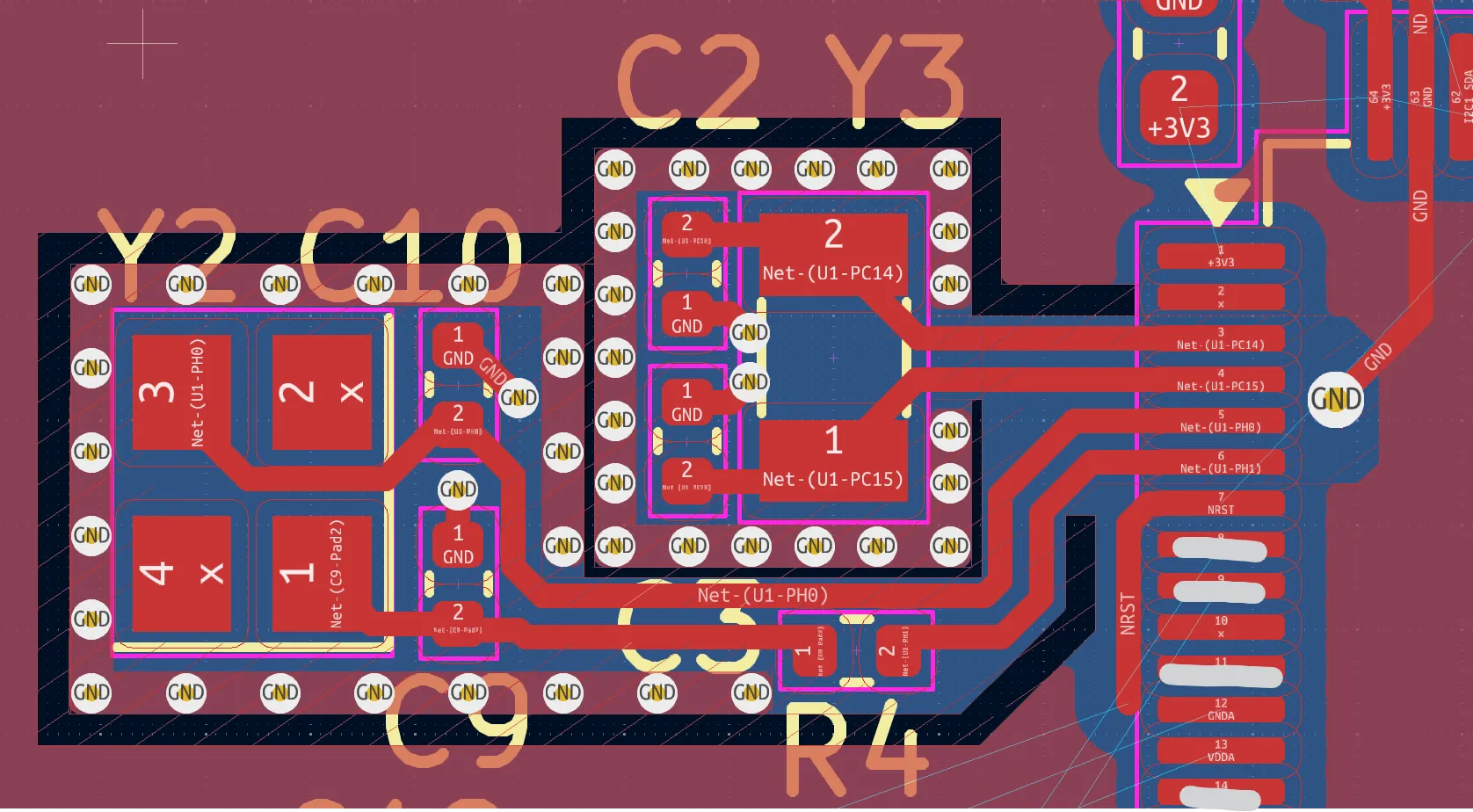
Once breadboard success confirms the design, etch or order a PCB for permanence. Keep crystal and capacitors within 5 mm of the inverter pins to minimize trace inductance. Route input and output traces as differential pairs with ground shielding. Place a ground plane under the oscillator section to reduce noise coupling.
Follow J-STD-001 requirements for soldering, using flux and preheated boards for clean joints. Avoid excessive heat on the crystal, which can shift frequency. Vias connect top ground pours to bottom planes effectively. Test post-assembly with the same scope method.
IPC-A-610 guidelines ensure joint acceptability, checking for voids or bridges. These practices yield stable performance in final projects.
PCB Layout Tips for Stable DIY Crystal Oscillators
Shorten traces between components to under 10 mm, as length introduces unwanted capacitance. Surround the oscillator area with a guard ring tied to ground, blocking EMI ingress. Avoid routing high-speed signals nearby, which couple noise into the circuit. Use 50-ohm impedance if buffering the output.
Decouple power pins with 100 nF and 10 uF capacitors in parallel. For multilayer PCBs, dedicate an inner layer to ground. Simulate layout parasitics if possible, though hobbyists rely on empirical tweaks. These steps maintain low phase noise.
Troubleshooting Common Issues in Crystal Oscillator Circuits
No oscillation often stems from incorrect load capacitance; measure and trim values iteratively. Weak signals indicate insufficient drive; reduce series resistor or check supply voltage. Frequency drift points to loose connections or temperature extremes. Use a frequency counter to diagnose precisely.
Overdrive damages crystals; monitor amplitude below 1 Vpp across the crystal. Parasitic oscillation from long leads requires shielding. Breadboard prototypes may fail on PCB due to ground bounce; add bypass caps. Systematic checks resolve most issues.
J-STD-020 handling prevents moisture issues during storage, baking components if needed. Clean flux residues per standards for longevity.
Advanced Variations for Hobbyists
Experiment with overtone modes for higher frequencies, adding inductors for mode selection. Low-frequency 32.768 kHz crystals suit battery-powered clocks with minimal power. Buffer the output with another gate for driving loads. These tweaks expand project possibilities.
Conclusion
Building a DIY crystal oscillator empowers hobbyists with precise timing control. From understanding piezoelectric principles to PCB implementation, each step builds practical expertise. Key practices like short traces and proper soldering ensure reliability. Troubleshooting hones diagnostic skills for future circuits. Integrate these into Arduino clocks or RF projects for satisfying results. Start simple, iterate, and enjoy stable oscillations.
FAQs
Q1: What components do I need for a basic DIY crystal oscillator?
A1: Essential crystal oscillator components include a quartz crystal, two 22 pF load capacitors, a 1 MOhm feedback resistor, and a 74HC04 inverter IC. Add decoupling capacitors and a 5V supply. This crystal oscillator circuit starts oscillating quickly on breadboard. Match capacitor values to the crystal datasheet for best stability. Total cost stays under a few dollars for hobbyists.
Q2: How do I build a crystal oscillator that won't start?
A2: Check load capacitors first, as mismatch prevents feedback. Verify inverter power and feedback resistor connection. Shorten breadboard jumps to reduce resistance. Test the crystal with a known working circuit. On PCB, confirm ground plane integrity. These steps fix most startup issues in your crystal oscillator tutorial.
Q3: What PCB layout rules apply to crystal oscillator circuits?
A3: Place the crystal close to IC pins with traces under 10 mm. Add a ground guard ring and a plane beneath. Decouple power thoroughly. Avoid noisy traces nearby. These practices minimize parasitics for stable DIY crystal oscillators.
Q4: Can I use a Colpitts circuit for my DIY crystal oscillator?
A4: Yes, Colpitts uses a transistor and split capacitors for feedback. It suits higher power needs versus Pierce. Select an NPN like 2N3904 with appropriate biasing. Tune capacitors for resonance. Great for audio or RF hobby projects, though Pierce is simpler for beginners.
References
J-STD-001G — Requirements for Soldered Electrical and Electronic Assemblies. IPC, 2017
IPC-A-610H — Acceptability of Electronic Assemblies. IPC, 2019
JEDEC J-STD-020E — Moisture/Reflow Sensitivity Classification of Nonhermetic Surface Mount Devices. JEDEC, 2014


