Introduction
Clock generators form the heartbeat of most electronic projects, providing the precise timing needed for digital circuits to function smoothly. For electronic hobbyists diving into microcontrollers, sensors, or simple logic gates, understanding clock generator basics is essential for reliable builds. Timing circuits rely on these components to synchronize operations, ensuring signals arrive when expected. Without a stable clock signal, even the simplest Arduino sketch or LED blinker can fail unpredictably. This guide breaks down the fundamentals, from basic concepts to practical tips, helping you create robust timing circuits on your breadboard or custom PCB. By the end, you’ll grasp how to select and implement clock generators for your next hobby project.
What Is a Clock Generator and Why Does It Matter?
A clock generator produces a clock signal, typically a square wave that alternates between high and low voltage levels at a consistent clock frequency. This periodic waveform acts as a timing reference, telling digital components when to perform actions like reading inputs or updating outputs. In hobbyist projects, clock generators matter because they prevent timing errors in circuits involving flip-flops, counters, or processors. For instance, a microcontroller running at 16 MHz needs a precise clock frequency to execute instructions correctly. Timing circuits built around clock generators enable everything from blinking LEDs at exact intervals to coordinating multiple sensors in a weather station. Mastering these basics empowers hobbyists to troubleshoot erratic behavior and scale up to more complex designs.
Oscillators vs Clock Generators: Key Differences
Oscillators and clock generators both create periodic signals, but they serve different roles in timing circuits. Basic oscillators generate a fundamental frequency using components like crystals or RC circuits, often outputting a sine wave or simple square wave. Clock generators, however, build on oscillators by incorporating dividers, multipliers, and phase-locked loops (PLLs) to produce multiple clock frequencies from a single source. Hobbyists often start with oscillators for straightforward needs, such as a 1 Hz square wave for a digital clock. In contrast, clock generators shine in projects requiring varied speeds, like driving a CPU at 100 MHz while feeding peripherals at lower rates. Understanding oscillators vs clock generators helps you choose the right tool, avoiding overkill for simple timing circuits.
RC circuits offer an accessible entry point for hobbyist oscillators. These use a resistor and capacitor to set the oscillation frequency via the time constant RC. A typical 555 timer IC configured as an astable multivibrator creates a square wave clock signal adjustable from audio frequencies up to several hundred kHz. While not as precise as crystal-based options, RC circuits tolerate minor component variations, making them forgiving for breadboard experiments. Precision improves with calibration, but for learning clock generator basics, they provide hands-on insight into timing circuits.
Technical Principles Behind Clock Generators
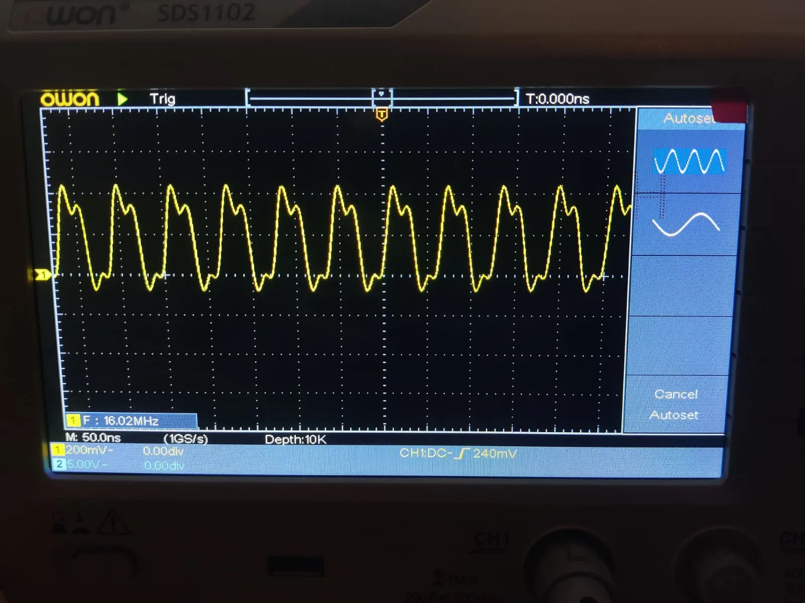
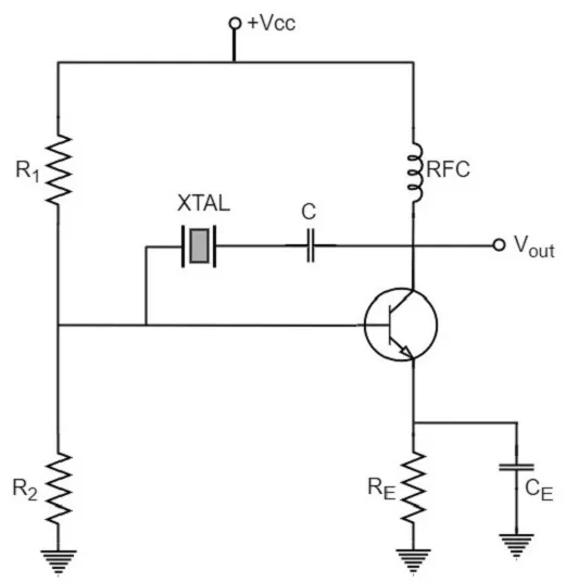
At their core, clock generators rely on feedback loops to maintain stable oscillation. A crystal oscillator, common in precise applications, uses a quartz crystal’s piezoelectric properties to resonate at a fixed frequency, typically between 1 MHz and 50 MHz. The crystal vibrates mechanically when electrified, feeding back a signal that the circuit amplifies into a clean square wave clock signal. External capacitors fine-tune the frequency, ensuring low jitter for reliable timing circuits. Hobbyists appreciate crystals for their accuracy, often within 50 ppm, far surpassing RC circuits.
Phase-locked loops enhance basic oscillators into full clock generators. A PLL compares the input clock signal’s phase to a feedback signal, adjusting output frequency via a voltage-controlled oscillator (VCO). This allows multiplication, say turning 25 MHz into 100 MHz, or division for slower clocks. In digital systems, PLLs minimize skew between multiple clock frequencies, crucial for synchronous designs. Noise from power supplies or nearby traces can disrupt PLL lock, so PCB layout plays a key role.
Square waves dominate clock signals due to their sharp transitions, ideal for triggering logic gates. The duty cycle, usually 50%, defines high and low time equality, computed as frequency’s inverse. Higher clock frequencies demand better signal integrity, as rise times shorten and EMI risks rise. For hobbyists, probing a square wave with a multimeter or scope reveals frequency and amplitude, aiding diagnosis. RC circuits approximate square waves but soften edges, suitable only for low-speed timing circuits.
Following IPC-2221 guidelines for PCB design ensures clock traces maintain controlled impedance, reducing reflections that distort clock frequency. Proper grounding and decoupling capacitors further stabilize oscillators vs clock generators setups.
Practical Solutions and Best Practices for Hobbyists
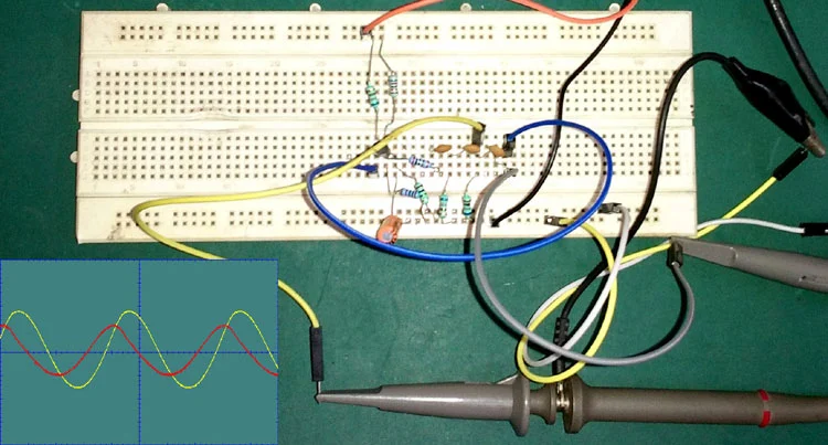
Start simple with through-hole oscillators on a breadboard to grasp clock generator basics. Modules outputting 8 MHz square waves plug directly into microcontroller pins, bypassing custom builds. For custom timing circuits, etch a PCB with an RC oscillator using a 555 IC, selecting R and C values via f = 1.44 / (R * 2C). Test frequency with an oscilloscope or frequency counter app on your phone. This hands-on approach builds intuition before tackling crystals.
When designing PCBs for clock generators, prioritize short traces for high clock frequencies to curb ringing. Place the oscillator near the load, routing clock signals as 50-ohm lines per IPC standards. Decouple power pins with 0.1 uF ceramics close to the IC, filtering noise that skews timing circuits. Hobbyists can use free layout tools to simulate, verifying square wave integrity before fabrication.
For multi-frequency needs, integrate a clock generator IC with PLL outputs. Configure via pins or resistors for desired clock frequencies, powering from a regulated 3.3V or 5V rail. In projects like a VGA generator, derive pixel clock from a base oscillator. Always verify duty cycle stays near 50% to avoid logic glitches.
Troubleshooting starts with scope checks: irregular square waves signal power issues or loading. Swap crystals if frequency drifts beyond spec. RC circuits drift with temperature, so calibrate periodically.
J-STD-001 requirements guide soldering oscillators, ensuring clean joints that preserve clock signal quality without solder bridges causing shorts.
Common Pitfalls and Troubleshooting Tips
Hobbyists often face jittery clocks from poor grounding. Use a star ground topology on PCBs, connecting all grounds to one point. Excessive capacitive loading slows rise times, distorting square waves; limit fanout or add buffers.
Overheating warps RC timing, so ventilate enclosures. Measure clock frequency under load to catch droops.
PLL unlock shows erratic outputs; check reference signal strength.
Conclusion
Clock generators underpin reliable timing circuits, from basic RC oscillators to advanced PLL-based designs. Grasping clock signal properties, square wave characteristics, and clock frequency selection equips hobbyists for success. Differentiating oscillators vs clock generators optimizes choices for projects. Adhering to standards like IPC-2221 elevates prototypes to production-ready boards. Experiment freely, measure often, and your timing circuits will pulse perfectly.
FAQs
Q1: What are the clock generator basics for a beginner timing circuit?
A1: Clock generator basics involve generating a stable square wave clock signal at a set clock frequency. Start with an RC circuit using a 555 timer for simple hobby projects, adjusting resistors and capacitors to tune the frequency. This setup teaches timing circuits without needing crystals. Test outputs with a scope to verify clean edges. Precision improves later with oscillators.
Q2: How do oscillators vs clock generators differ in practice?
A2: Oscillators produce a single frequency square wave or sine, ideal for basic timing circuits like LED blinkers. Clock generators add PLLs and dividers for multiple clock frequencies from one source, suiting complex microcontroller setups. Hobbyists pick oscillators for simplicity, clock generators for versatility. Both ensure synchronized clock signals.
Q3: Why is a square wave preferred for clock signals?
A3: Square waves provide sharp transitions that reliably trigger digital logic at precise clock frequency intervals. Unlike sine waves, they minimize ambiguity in state changes for timing circuits. RC circuits approximate this shape affordably. Proper PCB routing preserves edge quality.
Q4: Can RC circuits replace professional clock generators?
A4: RC circuits suit low-precision hobby timing circuits, generating adjustable square waves cheaply. They lack crystal stability for high clock frequencies but excel in learning clock generator basics. Calibrate for consistency. Upgrade to crystals for demanding projects.
References
IPC-2221B — Generic Standard on Printed Board Design. IPC, 2009
J-STD-001G — Requirements for Soldered Electrical and Electronic Assemblies. IPC, 2011
IPC-A-600K — Acceptability of Printed Boards. IPC, 2020


