Introduction
Surface Mount Technology, often abbreviated as SMT, stands as a cornerstone in modern PCB assembly. This method allows electronic components to be mounted directly onto the surface of printed circuit boards, enabling compact designs and high-speed production. For electric engineers, understanding SMT is vital to creating reliable and efficient electronic products. This guide explores the intricacies of the SMT process, from component placement to reflow soldering, while aligning with industry standards. It offers practical insights into best practices and troubleshooting techniques to ensure quality in PCB manufacturing. Whether you are designing intricate circuits or overseeing assembly lines, mastering SMT equips you with the tools to optimize performance and reduce defects in your projects.
What Is Surface Mount Technology and Why It Matters
Surface Mount Technology refers to a method where electronic components are placed and soldered directly onto the surface of a PCB, unlike traditional through-hole technology that requires leads to pass through drilled holes. SMT components are smaller, allowing for higher component density and enabling the miniaturization of electronic devices. This technology is critical in industries such as consumer electronics, automotive systems, and medical equipment, where space and performance are paramount.
The significance of SMT in PCB assembly lies in its ability to support automated production, reduce manufacturing costs, and improve reliability. By minimizing manual intervention, SMT enhances precision during component placement and soldering. For engineers, adopting SMT means faster assembly cycles and the ability to design complex, multi-layered boards. Its role in modern electronics cannot be overstated, as it directly impacts product functionality and market competitiveness.
Technical Principles of the SMT Process
The SMT process in PCB assembly involves several key stages, each governed by precise engineering principles. Understanding these steps ensures consistent quality and performance.
Solder Paste Application
The process begins with applying solder paste to the PCB. This paste, a mixture of tiny solder particles and flux, is deposited onto specific areas where components will be placed. A stencil, typically made of stainless steel, ensures accurate paste application on the pads. Precision in this step is crucial to avoid defects like insufficient solder or bridging between pads.
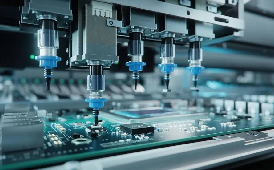
Component Placement
Next, automated machines, guided by design files, place components onto the solder paste. This step demands high accuracy to align components with their designated pads. Misalignment can lead to poor connections or assembly failures. The placement process often handles a variety of components, from resistors to complex integrated circuits, each requiring specific handling parameters.
Related Reading: Pick and Place Programming: A Step by Step Guide for PCB Assembly
Reflow Soldering
Reflow soldering follows component placement. The PCB passes through a reflow oven, where controlled heating melts the solder paste, forming permanent electrical and mechanical connections. The temperature profile in the oven typically includes preheating, soaking, reflow, and cooling zones. Each zone is carefully managed to prevent thermal shock to components or uneven soldering. Adhering to profiles specified in standards like IPC J-STD-020E is essential for reliability.

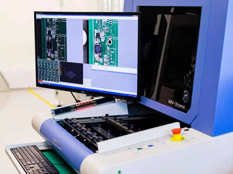
Inspection and Testing
After soldering, the assembled PCB undergoes inspection to detect defects such as solder bridges, tombstoning, or misaligned components. Techniques like Automated Optical Inspection and X-ray imaging are commonly used. Testing ensures that electrical connections meet design specifications and that the board functions as intended. Following guidelines from IPC-A-600K helps maintain quality during this phase.
Best Practices for Effective SMT Assembly
Achieving excellence in SMT assembly requires adherence to proven practices. These guidelines, rooted in industry standards, help engineers optimize the process and minimize errors in PCB manufacturing.
Design for Manufacturability
Start with a design that supports efficient assembly. Ensure pad sizes and spacing comply with recommendations in IPC-7351C for surface mount design. Proper spacing prevents soldering issues and facilitates automated placement. Additionally, include fiducial marks on the PCB to aid machine vision systems during component alignment.
Solder Paste and Stencil Precision
Select the appropriate solder paste based on component types and reflow requirements. Ensure the stencil aperture design matches the pad layout to avoid excess or insufficient paste. Regular cleaning of stencils prevents contamination and maintains consistency. Following IPC-7525B for stencil design can significantly improve paste application accuracy.
Optimized Reflow Profiles
Tailor the reflow profile to the specific components and board materials. Refer to IPC J-STD-020E for moisture sensitivity levels and reflow conditions to avoid damaging sensitive parts. Monitor peak temperatures and ramp rates to prevent thermal stress. A well-defined profile ensures uniform soldering across the board.
Component Handling and Storage
Handle components with care to avoid damage or contamination. Store moisture-sensitive devices according to JEDEC J-STD-033D guidelines to prevent issues like popcorn cracking during reflow. Use proper electrostatic discharge controls to protect sensitive electronics, aligning with IPC-ESD-2020 standards.
Regular Equipment Calibration
Maintain and calibrate assembly equipment regularly to ensure precision in component placement and soldering. Misaligned machines or inconsistent oven temperatures can lead to defects. Scheduled maintenance, guided by manufacturer specifications and industry practices, sustains production quality.
Troubleshooting Common SMT Assembly Issues
Even with best practices, challenges can arise during SMT assembly. Identifying and resolving these issues promptly is crucial for electric engineers focused on quality in PCB manufacturing.
Solder Bridging
Solder bridging occurs when excess solder connects adjacent pads, causing short circuits. This often results from too much solder paste or incorrect stencil design. Inspect the stencil apertures and reduce paste volume if necessary. Adjusting the reflow profile to ensure proper solder flow can also mitigate this issue.
Tombstoning
Tombstoning happens when a component stands upright on one end due to uneven heating or solder wetting. Balance the thermal profile across the board and verify pad designs are symmetrical. Ensuring consistent solder paste application on both pads of a component helps prevent this defect.
Component Misalignment
Misaligned components disrupt electrical connections and functionality. This issue often stems from inaccurate placement data or machine calibration errors. Review the design files and machine settings. Adding or adjusting fiducial marks can improve alignment accuracy during placement.
Insufficient Solder Joints
Weak or insufficient solder joints lead to unreliable connections. Causes include inadequate paste volume or improper reflow temperatures. Check the stencil design and confirm the reflow profile aligns with IPC J-STD-020E specifications. Increasing paste thickness or adjusting oven settings may resolve the problem.
Related Reading: SMT Testing in SMT PCB Assembly Process
Conclusion
Surface Mount Technology remains a pivotal aspect of PCB assembly, driving innovation in electronics through compact and efficient designs. By grasping the core principles of the SMT process, from precise component placement to controlled reflow soldering, electric engineers can enhance product reliability and performance. Implementing best practices, adhering to industry standards, and addressing common issues proactively ensures high-quality outcomes in PCB manufacturing. As technology evolves, staying informed about SMT advancements will keep your projects at the forefront of industry standards and expectations.
FAQs
Q1: What are the key benefits of Surface Mount Technology in PCB assembly?
A1: Surface Mount Technology offers significant advantages in PCB assembly, including higher component density for compact designs and compatibility with automated production. This reduces labor costs and improves precision. SMT also supports faster assembly cycles, making it ideal for high-volume manufacturing while maintaining reliability through standardized processes.
Q2: How does reflow soldering impact the SMT process?
A2: Reflow soldering is critical in the SMT process as it creates permanent connections between components and the PCB. Controlled heating in a reflow oven melts solder paste, forming reliable joints. Proper temperature profiling prevents defects like thermal shock, ensuring consistent quality across the board.
Q3: What causes component placement errors in PCB manufacturing?
A3: Component placement errors in PCB manufacturing often result from incorrect design data, machine calibration issues, or lack of fiducial marks. These errors can lead to misaligned parts and poor connections. Regular equipment checks and accurate design files help minimize such issues during assembly.
Q4: How can engineers prevent defects during the SMT process?
A4: Engineers can prevent defects in the SMT process by adhering to standards like IPC-7351C for design and IPC J-STD-020E for reflow conditions. Proper stencil design, calibrated equipment, and controlled storage of components also reduce risks of bridging, tombstoning, and other common issues.
References
IPC-7351C — Generic Requirements for Surface Mount Design and Land Pattern Standard. IPC, 2018.
IPC J-STD-020E — Moisture/Reflow Sensitivity Classification for Nonhermetic Surface Mount Devices. IPC/JEDEC, 2014.
IPC-A-600K — Acceptability of Printed Boards. IPC, 2020.
IPC-7525B — Stencil Design Guidelines. IPC, 2012.
JEDEC J-STD-033D — Handling, Packing, Shipping, and Use of Moisture, Reflow, and Process Sensitive Devices. JEDEC, 2018.
IPC-ESD-2020 — Joint Standard for Electrostatic Discharge Control Program Development. IPC, 2020.


