Introduction
Through Hole Technology, commonly known as THT, remains a cornerstone in electronics assembly, especially for components requiring robust mechanical connections. Selecting the right solder for THT assembly directly impacts joint reliability, manufacturing efficiency, and long term performance of printed circuit boards. This guide explores the best solder for THT, compares leaded versus lead free solder, and outlines various solder types suited for electronics applications. Aimed at electrical engineers and assembly professionals, this article provides practical insights into making informed decisions for optimal soldering results in THT processes. Whether you're working on prototypes or high volume production, understanding solder properties and their compatibility with THT assembly is essential. Let's dive into the technical aspects and best practices to ensure strong, reliable solder joints.
What Is THT Assembly and Why Solder Selection Matters
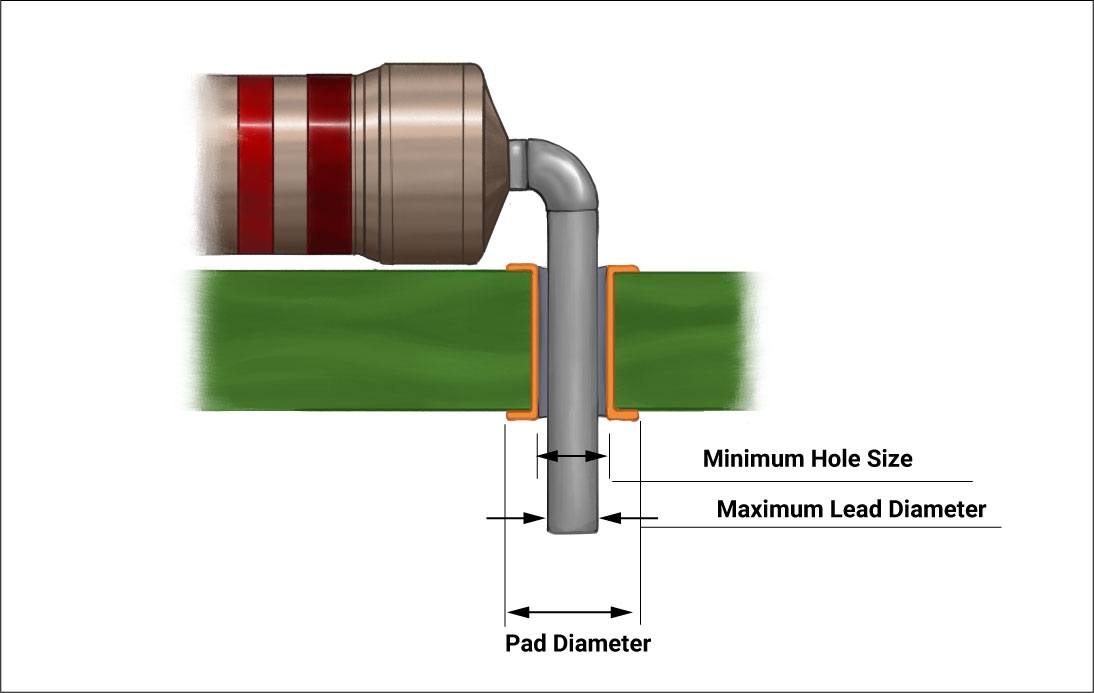
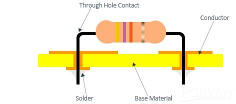
Through Hole Technology involves inserting component leads into drilled holes on a printed circuit board, followed by soldering to create electrical and mechanical connections. THT is widely used for components like connectors, capacitors, and power devices due to its durability under mechanical stress. The choice of solder in THT assembly is critical as it affects the quality of the joint, ease of application, and compliance with industry standards.
Solder selection influences thermal performance, wetting characteristics, and long term reliability of the assembly. Poor solder choices can lead to weak joints, cold solder defects, or thermal fatigue over time. Additionally, regulatory requirements often dictate whether leaded or lead free solder is permissible. For engineers, balancing performance with environmental and safety considerations is a key challenge in THT soldering processes.
Technical Principles of Solder in THT Assembly
Solder Composition and Properties
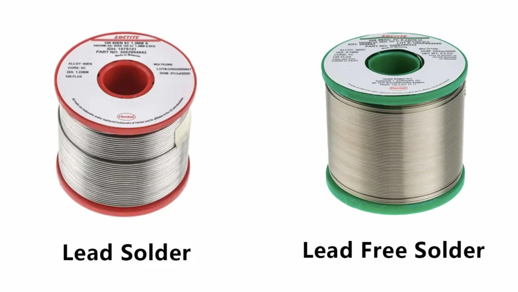
Solder is a fusible metal alloy used to create permanent bonds between electronic components and PCB pads. In THT assembly, solder must flow into the through holes, wet the component leads, and form a strong intermetallic bond with the board's copper pads. The two primary categories are leaded and lead free solder, each with distinct compositions and melting points.
Leaded solder, typically a tin lead alloy like 63 percent tin and 37 percent lead, offers a lower melting point, around 183 degrees Celsius, as per industry standards. This lower temperature eases the soldering process and reduces thermal stress on components. On the other hand, lead free solder, often composed of tin, silver, and copper, has a higher melting point, typically around 217 to 220 degrees Celsius, requiring more precise control during soldering to avoid component damage.
Wetting and Flow Characteristics
Wetting refers to the ability of molten solder to spread over a surface, forming a smooth, uniform bond. In THT, good wetting ensures the solder fills the hole and adheres to both the lead and the pad. Leaded solder generally exhibits superior wetting compared to lead free options due to its composition. However, advancements in lead free alloys have improved their performance, making them viable for many applications, as outlined in standards like IPC J-STD-006C.
Flow characteristics determine how well solder moves into tight spaces within through holes. Proper flow prevents voids or incomplete joints, which can compromise electrical conductivity and mechanical strength. Engineers must consider flux compatibility and soldering temperature to optimize flow in THT processes.
Thermal and Mechanical Considerations
THT components often endure mechanical stress, especially in applications like automotive or industrial electronics. Solder must withstand vibration, thermal cycling, and physical strain without cracking. Leaded solder tends to be more ductile, absorbing stress better than some lead free alternatives, which can be brittle under certain conditions. Standards such as IPC-A-610H provide guidelines on acceptable solder joint characteristics to ensure reliability under stress.
Leaded vs Lead Free Solder: A Detailed Comparison
Performance in THT Assembly
When choosing the best solder for THT, the debate between leaded and lead free options often arises. Leaded solder is historically preferred for its ease of use and reliability. Its lower melting point reduces the risk of thermal damage to sensitive components during soldering. Additionally, leaded solder forms more consistent joints with fewer defects like incomplete wetting, as noted in various industry studies aligned with IPC standards.
Lead free solder, driven by environmental regulations like the Restriction of Hazardous Substances directive, is now mandatory in many regions for commercial electronics. While it offers comparable performance in many cases, its higher melting point demands careful temperature control during THT soldering. This can increase the risk of board warpage or component stress if not managed per guidelines in IPC-6012E.
Suggested Reading: Stencil Printing with Lead Free Solder Paste: Best Practices for Reliable Assembly
Regulatory and Environmental Impact
Environmental considerations play a significant role in solder selection. Lead free solder aligns with global efforts to reduce hazardous materials in electronics. However, the manufacturing of lead free alloys often involves more energy due to higher processing temperatures, which can offset some environmental benefits. Engineers must weigh these factors alongside performance needs when selecting solder types for THT assembly.
Cost and Availability
Cost is another factor in the leaded versus lead free debate. Leaded solder is generally less expensive and widely available for non regulated applications like hobbyist projects or specific industrial uses. Lead free solder, while more costly due to alloy complexity, is the standard in most commercial production environments. Availability of both types depends on regional regulations and supply chain dynamics.
Solder Types for THT Assembly
Common Alloys and Their Applications
Several solder types are suitable for THT assembly, each with unique properties. For leaded solder, the 63/37 tin lead alloy is a popular choice due to its eutectic nature, meaning it transitions directly from solid to liquid without a pasty phase, ensuring smooth joints. This alloy is ideal for general purpose THT soldering where regulations permit.
For lead free options, tin silver copper alloys, often referred to by their SAC designation, are widely used. These alloys provide good mechanical strength and thermal resistance, making them suitable for high reliability applications. Other lead free solder types include tin copper or tin bismuth alloys, though they are less common in THT due to specific performance limitations.
Flux Core and No Clean Options
Solder for THT assembly often comes with a flux core to aid wetting and remove oxides from surfaces during soldering. Rosin based flux is traditional and effective but may require cleaning to prevent residue buildup, as per IPC-A-600K guidelines. No clean flux options are increasingly popular, minimizing post soldering cleanup while maintaining joint integrity, provided they meet acceptability criteria in standards like IPC-A-610H.
Wire Diameter and Form Factors
Solder wire diameter affects precision in THT assembly. Thinner wires, around 0.5 to 0.8 millimeters, are suitable for fine pitch components or rework, while thicker wires, around 1.0 to 1.6 millimeters, are better for larger through holes requiring more solder volume. Selecting the appropriate diameter ensures efficient application without excess material waste.
Practical Solutions for Solder Selection in THT Assembly
Assessing Application Requirements
Start by evaluating the specific needs of your THT assembly project. Consider the operating environment, mechanical stress, and thermal cycling the assembly will face. High reliability applications, such as aerospace or medical devices, may prioritize lead free solder for compliance with strict standards, while prototyping might favor leaded solder for ease of use.
Matching Solder to Equipment and Process
Ensure your soldering equipment can handle the chosen solder type. Lead free solder requires higher temperatures, so soldering irons or wave soldering systems must maintain consistent heat without exceeding component limits outlined in JEDEC J-STD-020E. Adjust process parameters like preheat time and soldering duration to match the solder's melting point and flow characteristics.
Testing and Validation
Before full scale production, conduct small batch testing to validate solder performance. Inspect joints for wetting, fillet formation, and voiding using visual and X ray methods as recommended by IPC-A-610H. Testing under simulated operating conditions can reveal potential issues like thermal fatigue or mechanical failure, allowing adjustments before mass assembly.
Troubleshooting Common Solder Issues in THT Assembly
Cold Solder Joints
Cold solder joints appear dull and uneven, often due to insufficient heat or poor wetting. Ensure the soldering iron tip reaches the correct temperature for the chosen solder type. Applying flux can improve wetting if contamination is suspected. Standards like IPC-A-610H define acceptable joint appearance to guide troubleshooting.
Suggested Reading: Troubleshooting Cold Solder Joints: Hot Air Rework to the Rescue!
Incomplete Hole Fill
In THT, incomplete hole fill can weaken connections. This issue often stems from inadequate solder volume or poor flow. Increase preheat time or adjust wave soldering parameters to ensure molten solder fully penetrates the through hole. Verify compliance with joint fill criteria in IPC-A-600K during inspection.
Bridging and Excess Solder
Solder bridging between adjacent holes or excess buildup can cause shorts. Use the correct solder wire diameter and control application speed to avoid overuse. If bridging occurs, remove excess with a desoldering tool and reapply solder carefully, adhering to best practices in IPC standards.
Conclusion
Selecting the right solder for THT assembly is a critical decision that influences the quality and reliability of electronic products. By understanding the differences between leaded and lead free solder, evaluating various solder types, and applying practical selection criteria, engineers can achieve optimal results in through hole soldering. Adhering to industry standards ensures compliance and performance, whether for prototyping or high volume production. With careful consideration of application needs and process compatibility, the best solder for THT can be identified to meet both technical and regulatory demands.
FAQs
Q1: What is the best solder for THT assembly in high reliability applications?
A1: For high reliability applications like aerospace or medical electronics, lead free solder, such as tin silver copper alloys, is often the best choice due to regulatory compliance and strong mechanical properties. Ensure soldering equipment supports the higher melting points, around 217 degrees Celsius, and validate joint quality per IPC-A-610H standards for durability under stress.
Q2: How does leaded vs lead free solder impact THT soldering processes?
A2: Leaded solder, with a lower melting point of about 183 degrees Celsius, is easier to work with and less likely to cause thermal damage in THT soldering. Lead free solder requires higher temperatures, around 217 degrees Celsius, necessitating precise control to avoid component stress. Both can form reliable joints if processes align with IPC guidelines.
Q3: Which solder types are most compatible with THT for prototyping?
A3: For prototyping, leaded solder types like 63/37 tin lead alloys are often preferred due to their ease of use and lower melting point. They allow quick adjustments without risking thermal damage to components. If regulations apply, consider lead free options with no clean flux to simplify rework while meeting basic compliance.
Q4: How can I ensure proper wetting with lead free solder in THT assembly?
A4: To ensure proper wetting with lead free solder in THT assembly, use adequate flux to remove oxides and preheat the board to improve solder flow. Maintain soldering temperatures around 217 to 220 degrees Celsius as needed. Follow IPC J-STD-006C guidelines for alloy selection and inspect joints visually per IPC-A-610H standards.
References
IPC-A-610H — Acceptability of Electronic Assemblies. IPC, 2021.
IPC-A-600K — Acceptability of Printed Boards. IPC, 2020.
IPC-6012E — Qualification and Performance Specification for Rigid Printed Boards. IPC, 2020.
IPC J-STD-006C — Requirements for Electronic Grade Solder Alloys and Fluxed and Non-Fluxed Solid Solders for Electronic Soldering Applications. IPC, 2013.
JEDEC J-STD-020E — Moisture/Reflow Sensitivity Classification for Nonhermetic Surface Mount Devices. JEDEC, 2014.


