Introduction
Surface mount technology has transformed PCB assembly by enabling smaller, more efficient designs, and SMD crystal oscillators stand at the forefront of this evolution. These compact devices provide precise clock signals essential for synchronizing digital circuits in everything from portable gadgets to industrial controls. Electric engineers rely on SMD crystal oscillators for their reliability in high-density boards where space and performance are critical. This guide delves into their workings, package options, benefits, and real-world use, offering practical insights for seamless integration. Understanding these components ensures optimal timing accuracy and assembly success in demanding applications.
What Is an SMD Crystal Oscillator and Why It Matters
An SMD crystal oscillator is an active electronic component that generates a stable, accurate frequency output using a quartz crystal and integrated oscillator circuit, designed specifically for surface mount assembly. Unlike passive crystals, which require external circuitry, these oscillators deliver a ready-to-use square wave or CMOS-compatible signal directly. Their surface mount package eliminates through-hole leads, aligning perfectly with automated SMT processes on modern PCBs. Engineers value them for maintaining frequency stability across temperature variations and loads, crucial in systems where timing jitter can cause failures.
In the PCB industry, SMD crystal oscillators matter because they support miniaturization trends in consumer electronics and IoT devices. High-density boards demand low-profile components to reduce overall stack height and improve thermal management during reflow soldering. They adhere to assembly standards like IPC-A-610 for solder joint acceptability, ensuring robust mechanical and electrical connections. Without precise timing from these oscillators, microcontrollers and processors face synchronization issues, leading to erratic behavior in real-time systems. Selecting the right SMD crystal oscillator prevents costly redesigns and field failures.
Technical Principles of SMD Crystal Oscillators
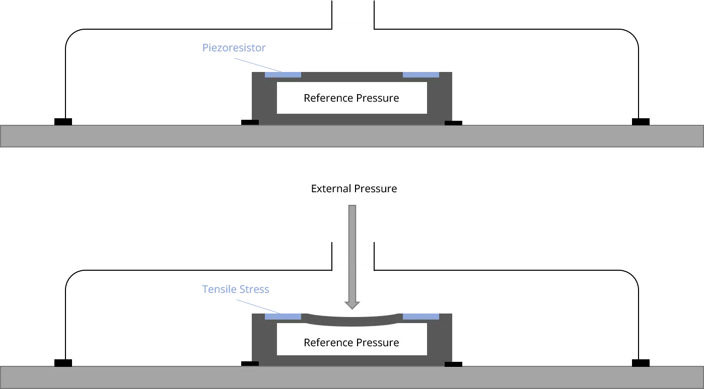
SMD crystal oscillators operate on the piezoelectric effect, where mechanical stress on a quartz crystal produces voltage, and vice versa, creating resonance at a specific frequency. The internal circuit amplifies this vibration to sustain oscillation, typically in fundamental mode for frequencies up to 50 MHz or overtone for higher ranges. Engineers must consider the equivalent series resistance (ESR) and load capacitance to match PCB parasitics, avoiding startup failures or instability. Output waveform shaping ensures clean edges for digital logic compatibility, minimizing EMI through controlled rise times.
Temperature compensation plays a key role, as quartz exhibits parabolic frequency drift; many SMD crystal oscillators include trimming capacitors for calibration. Aging effects, where frequency shifts over time due to crystal stress relaxation, demand stability specs like ±10 ppm over operating life. Power supply noise rejection via internal regulation keeps jitter low, typically under 1 ps RMS. Troubleshooting starts with verifying supply voltage within 1.8V to 3.3V tolerances, as undervoltage causes mode-hopping.
SMD Crystal Oscillator Package Types
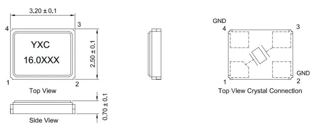
SMD crystal oscillators come in standardized ceramic packages optimized for pick-and-place accuracy and reflow compatibility. Common sizes include 3.2 x 2.5 mm (3225), ideal for general-purpose clocks with heights around 0.8 to 1.2 mm; 2.5 x 2.0 mm (2520) for tighter spaces; and 2.0 x 1.6 mm (2016) for ultra-compact designs. Smaller 1.6 x 1.2 mm options suit wearables, while 32.768 kHz tuning fork types often use 3.2 x 1.5 mm for real-time clocks. Most feature four pads: VCC, GND, output, and NC or enable pin, with tolerances per IPC-7351 for land pattern design.
Package selection hinges on board space, frequency range, and environmental needs. Ceramic hermetic sealing protects against humidity, classified under IPC/JEDEC J-STD-020 for moisture sensitivity levels (MSL 1 to 3 typically). Engineers should verify footprint dimensions to prevent tombstoning during reflow, using 0.3 to 0.5 mm pad widths. Larger packages like 5.0 x 3.2 mm offer better thermal dissipation for high-frequency units. Always cross-check datasheet tolerances against assembly processes for reliable yields.
- 3.2 x 2.5 mm — Typical Height: 0.9-1.2 mm; Common Frequencies: 8-50 MHz; Applications: Microcontrollers, comms
- 2.5 x 2.0 mm — Typical Height: 0.7-1.0 mm; Common Frequencies: 12-40 MHz; Applications: IoT sensors
- 2.0 x 1.6 mm — Typical Height: 0.5-0.8 mm; Common Frequencies: 16-32 MHz; Applications: Wearables
- 1.6 x 1.2 mm — Typical Height: 0.4-0.6 mm; Common Frequencies: 24-48 MHz; Applications: Mobile devices
Advantages of SMD Crystal Oscillators
SMD crystal oscillators offer superior space efficiency over through-hole types, reducing PCB real estate by up to 70% in dense layouts. Their low profile minimizes Z-axis height, aiding stacked assemblies in handheld devices. Automated SMT compatibility boosts throughput, with high placement accuracy from fiducial marks and taped reels. Stability metrics like ±10-50 ppm surpass RC oscillators, ensuring reliable timing in noisy environments.
Thermal performance excels due to direct board coupling, dissipating heat effectively without sockets. Cost savings arise from fewer process steps and higher yields in volume production. EMI shielding via grounded metal lids cuts radiation, complying with FCC limits. Engineers appreciate quick startup times under 5 ms, ideal for battery-powered systems. Overall, these advantages streamline design-to-manufacture workflows.
Applications of SMD Crystal Oscillators
In telecommunications, SMD crystal oscillators clock baseband processors and RF transceivers, demanding low phase noise for signal integrity. Automotive ECUs use them for CAN bus timing, enduring vibration and -40°C to +125°C ranges. Consumer gadgets like smartphones integrate 26 MHz units for Wi-Fi/Bluetooth sync. IoT nodes leverage low-power 32 kHz variants for sleep-mode accuracy.
Medical devices rely on high-stability oscillators for sensor data logging, where drift affects diagnostics. Industrial PLCs employ overtone models for motor control precision. Networking gear benefits from multi-output options syncing multiple rails. Troubleshooting application issues often traces to mismatched stability specs, resolved by selecting extended temp grades.
Best Practices for PCB Integration and Assembly
Layout SMD crystal oscillators near the load IC with short traces under 20 mm to minimize parasitic capacitance. Place decoupling caps (0.1 μF ceramic) within 2 mm of VCC pin, using vias for ground return. Follow IPC-7351 land patterns for optimal solder paste volume, avoiding under-etching that causes opens. Pre-bake components per J-STD-020 MSL ratings before reflow to prevent popcorning.
Reflow profiles peak at 260°C max, with 60-120 s above 217°C for Pb-free alloys. Inspect joints per IPC-A-610 Class 2 or 3 criteria, checking for voids under 25% area. Enable pin control saves power in burst modes. Signal integrity tools verify jitter post-assembly. These steps yield robust boards with minimal rework.
Troubleshooting Common Issues with SMD Crystal Oscillators
No output signal often stems from power supply glitches; measure ripple below 50 mV and confirm voltage sag during startup. Frequency drift points to load mismatch or mechanical stress from board flex, addressed by guard rings and conformal coating. High jitter arises from ground bounce, fixed by solid planes and ferrite beads on VCC.
Reflow defects like head-in-pillow show as intermittent contacts; optimize stencil apertures to 110% pad size. ESD damage mimics opens, so use Class 1A handling per IEC 61000-4-2. Temp cycling reveals aging; test per JEDEC profiles. Oscilloscope probing with 10x probes diagnoses waveform distortion. Systematic checks restore functionality efficiently.
Conclusion
SMD crystal oscillators enable compact, reliable timing solutions critical for modern PCBs, balancing size, stability, and manufacturability. Key package types like 3225 and 2016 cater to diverse needs, while advantages in automation and performance drive their adoption. Best practices in layout, assembly per standards, and troubleshooting ensure long-term success. Engineers gain confidence integrating these components, avoiding pitfalls in high-volume production. Prioritize specs matching application demands for optimal results.
FAQs
Q1: What are the main advantages of SMD crystal oscillators over through-hole types?
A1: SMD crystal oscillators excel in space savings and automated assembly, fitting high-density PCBs with profiles under 1.2 mm. They offer better thermal coupling and faster production cycles, reducing costs. Stability remains high with low jitter, ideal for electric engineers optimizing board real estate. Proper land patterns per IPC-7351 enhance reliability during reflow.
Q2: What are common SMD crystal oscillator package types and their uses?
A2: Popular SMD crystal oscillator package types include 3.2 x 2.5 mm for versatile clocks, 2.0 x 1.6 mm for mobiles, and 1.6 x 1.2 mm for ultra-small apps. Selection depends on frequency and height needs. Ceramic 4-pad designs suit SMT lines, with MSL ratings per J-STD-020 guiding handling. Match footprints to avoid defects.
Q3: What are typical applications for surface mount crystal oscillators?
A3: Surface mount crystal oscillators drive timing in IoT, automotive ECUs, telecom, and wearables, providing stable clocks for MCUs and RF. Low-power 32 kHz types power RTCs, while high-freq units sync processors. They withstand harsh environments with proper grading. Troubleshooting focuses on EMI and temp drift for peak performance.
Q4: How do you select the right SMD crystal oscillator for a PCB design?
A4: Evaluate frequency stability, operating temp, package size, and output logic for your SMD crystal oscillator needs. Check MSL via J-STD-020 for assembly fit. Verify startup time and jitter specs against system reqs. Consult datasheets for PCB layout tips to prevent issues like no-start. Test prototypes early.
References
IPC-7351C — Generic Requirements for Surface Mount Design and Land Pattern Standard. IPC, 2010
IPC/JEDEC J-STD-020F — Moisture/Reflow Sensitivity Classification for Nonhermetic Surface Mount Devices. IPC/JEDEC, 2021
IPC-A-610H — Acceptability of Electronic Assemblies. IPC, 2019