Introduction
ICT Testing is an automated electrical test method used to verify the quality and integrity of circuit board assemblies. It performs a comprehensive check of individual components and the numerous electrical contacts on a populated PCB. The primary purpose of ICT is to confirm that components are correctly installed and that all electrical connections are sound. By doing so, it detects a wide range of assembly defects such as shorts, opens, missing parts, incorrect component values, and misoriented components.
The significance of ICT Testing for board assemblies cannot be overstated. Catching defects early in the manufacturing process significantly reduces rework costs and improves overall product reliability. Imagine finding a faulty resistor only after the product has been fully assembled and packaged. The cost and time associated with disassembling, repairing, and reassembling that product would be substantial. ICT helps us avoid these costly scenarios by pinpointing issues at the component level, ensuring that each board assembly meets its design specifications before proceeding to more expensive functional tests or final product integration.
Technical Principles: How ICT Utilizes Fixtures and Electrical Contacts
The core of ICT Testing relies on precise electrical measurements. An ICT system works by applying test signals to individual nodes on the board assembly and then measuring the corresponding electrical responses. This process requires dedicated hardware and specialized software.
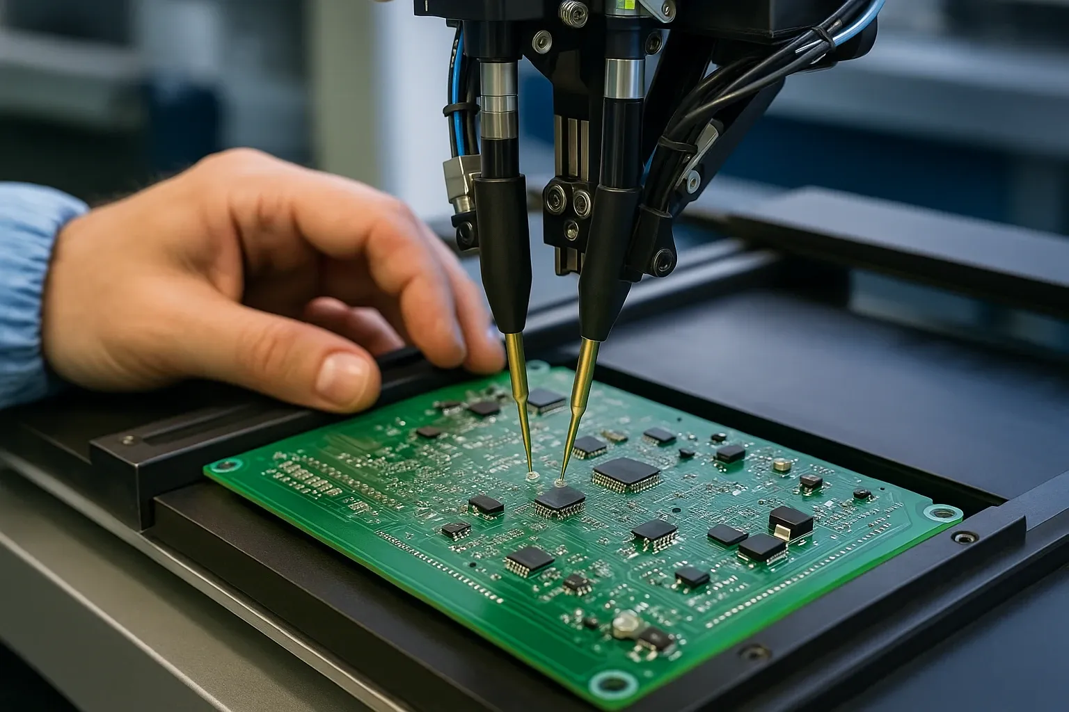
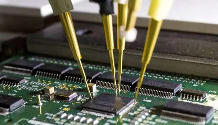
At the heart of the ICT system is the fixture, often referred to as a "bed-of-nails" fixture. This is a custom-designed mechanical interface specific to each PCB design. The fixture holds the board assembly securely in place during testing. It contains an array of spring-loaded pins, also known as pogo pins, which act as electrical contacts. These pins are precisely aligned to make contact with designated test points or pads on the board.
The selection and placement of these test points are crucial. Good Design for Testability (DfT) practices dictate that designers include sufficient test points to achieve adequate test coverage. Without accessible test points, the ICT system cannot make the necessary electrical contacts to verify component parameters or circuit continuity.
Once the board assembly is placed into the fixture and the electrical contacts are established, the ICT machine performs a series of tests. These tests can measure various electrical parameters:
- Resistance: Checking resistor values against specified tolerances.
- Capacitance: Verifying capacitor values.
- Inductance: Measuring inductor values.
- Continuity: Detecting open circuits where connections should exist.
- Shorts: Identifying unintended connections between traces or component pins.
The test program, developed specifically for each board, controls the sequence of these measurements. It compares the measured values against a predefined set of expected values and tolerances. Any deviation signals a potential defect, and the system generates a fault report detailing the location and nature of the issue.
Related Reading: What You Need to Know Before Designing an ICT Test Fixture
Identifying Common Assembly Defects with ICT Testing
ICT Testing excels at finding specific manufacturing-related assembly defects that can occur during the PCB assembly process. These defects typically involve improper component placement or soldering issues. Here are some of the common issues ICT can detect:
- Short Circuits: These occur when solder unintentionally bridges two adjacent traces or component leads, creating an unwanted electrical path. ICT can quickly identify these by measuring abnormally low resistance between two points that should be isolated.
- Open Circuits: This defect means an intended electrical connection is missing. This could be due to a poor solder joint, a broken trace, or a component lead not making proper contact. ICT detects opens by measuring infinite resistance or a lack of continuity.
- Missing Components: Sometimes a component may not be placed on the board during automated assembly. ICT identifies this by checking for the electrical characteristics of the missing component.
- Incorrect Components: Using the wrong resistor value, an incorrect capacitor, or even a different type of integrated circuit can lead to functional problems. ICT measures the electrical parameters of each component to ensure it matches the Bill of Materials (BOM).
- Misoriented Components: Polarized components like diodes, electrolytic capacitors, and some integrated circuits must be oriented correctly. An ICT system can detect reversed polarity by checking their electrical behavior.
- Solder Joint Quality: While not a visual inspection, ICT can infer poor solder joints if they result in opens, shorts, or incorrect electrical values.
ICT's ability to isolate these component-level faults quickly is a major advantage. Unlike functional testing, which might only indicate a board failure without pinpointing the exact cause, ICT provides precise diagnostic information. This detailed feedback helps assembly engineers efficiently troubleshoot and repair faulty board assemblies.
Related Reading: ICT Test Fixtures for PCB Testing: A Component-Level Verification Guide
Practical Solutions and Best Practices for Effective ICT
Implementing effective ICT Testing involves several best practices, especially considering the constraints of modern PCB designs.
- Design for Testability (DfT): This is paramount. Designers must incorporate sufficient test points and access pads on the PCB layout during the design phase. This ensures that the ICT fixture can make reliable electrical contacts for comprehensive testing. IPC-2221B, "Generic Standard on Printed Board Design," provides guidelines that can aid in planning for testability. Adequate spacing around components and accessible traces are key.
- Fixture Design and Maintenance: A robust and accurate fixture is vital for consistent test results. The fixture needs precise alignment mechanisms to ensure every pogo pin makes proper contact. Regular maintenance, including cleaning and replacing worn or bent probes, is essential to prevent false failures.
- Comprehensive Test Program Development: The ICT test program must be meticulously developed to cover as many potential assembly defects as possible. This involves importing design data, generating test vectors, and setting appropriate pass/fail limits for each measurement.
- Integration into the Manufacturing Flow: ICT is most effective when integrated early in the assembly process, ideally after reflow soldering. This allows for early detection and repair, minimizing the cost of rework.
- Data Analysis and Process Improvement: Analyzing ICT failure data provides valuable insights into recurring manufacturing issues. This information can be used to identify process bottlenecks or common defect types, leading to continuous improvement in the assembly line. For instance, repeated failures due to shorts might indicate a problem with solder paste application or reflow profiling.
Troubleshooting Common ICT-Related Issues in Board Assemblies
Even with best practices, challenges can arise in ICT. As an assembly engineer, troubleshooting these issues is a routine part of ensuring smooth production.
One common problem is false failures. These occur when the ICT system reports a defect that does not actually exist on the board. Common causes include:
- Poor electrical contacts: Dirt or residue on test points, worn pogo pins, or misalignment of the fixture can prevent proper contact. Regularly cleaning the fixture and inspecting probes can mitigate this.
- Guarding issues in the test program: Incorrect guarding can cause a component to appear faulty due to current paths through other parts of the circuit. This requires careful adjustment of the test program.
Another challenge is optimizing test coverage. For complex or high-density board assemblies, physical access for test probes can be limited. Designers must balance the desire for 100% test coverage with the practicalities of board space and cost. Sometimes, alternative testing methods like Automated Optical Inspection (AOI) or Automated X-ray Inspection (AXI) are used in conjunction with ICT to provide a more complete picture of quality. While ICT verifies electrical integrity, AOI/AXI can inspect for visual and hidden defects that ICT might miss.
Debugging real assembly defects found by ICT requires a systematic approach. The detailed fault reports from the ICT system are invaluable. They guide technicians directly to the faulty component or connection, allowing for efficient repair in accordance with standards such as J-STD-001G, "Requirements for Soldered Electrical and Electronic Assemblies," which outlines criteria for acceptable soldering. Furthermore, IPC-A-610G, "Acceptability of Electronic Assemblies," provides visual acceptance criteria for various aspects of populated boards.
Conclusion
ICT Testing is an indispensable part of modern PCB assembly. It acts as a robust gatekeeper, ensuring the quality and reliability of board assemblies by meticulously checking each component and every electrical contact. By leveraging a specialized fixture and comprehensive test programs, ICT efficiently identifies a broad spectrum of assembly defects, from shorts and opens to incorrect or misoriented components. Integrating effective DfT practices and maintaining test equipment are crucial for maximizing the benefits of ICT, ultimately leading to higher quality products and reduced manufacturing costs.
FAQs
Q1: What types of assembly defects can ICT Testing detect?
A1: ICT Testing is highly effective at identifying a variety of assembly defects including short circuits, open circuits, missing components, incorrect component values, and misoriented components like diodes or integrated circuits. It also verifies the presence and correct electrical values of passive components such as resistors, capacitors, and inductors. These checks ensure the basic electrical integrity of the board assemblies.
Q2: How does an ICT fixture connect to the board assemblies?
A2: An ICT fixture typically uses a "bed-of-nails" design. This involves a custom-made plate containing numerous spring-loaded pins, or pogo pins. When a board assembly is placed into the fixture, these pins align precisely with designated test points or pads on the PCB, creating reliable electrical contacts. This physical connection allows the ICT tester to send and receive electrical signals for comprehensive testing.
Q3: Why are precise electrical contacts crucial for accurate ICT Testing?
A3: Precise electrical contacts are fundamental to accurate ICT Testing. If the test probes do not make consistent and reliable contact with the test points on the board assemblies, false failures can occur, or actual assembly defects might be missed. Good contact ensures that accurate electrical measurements are taken, allowing the ICT system to correctly identify discrepancies against specified component values and circuit continuity.
Q4: What are the limitations of ICT Testing for complex PCBs?
A4: While powerful, ICT Testing has limitations, especially with increasingly complex board assemblies. Densely packed boards can have limited physical access for test points, potentially restricting test coverage. ICT also primarily focuses on manufacturing defects and component presence; it generally cannot detect functional performance issues, timing problems, or intermittent faults that only appear under specific operating conditions. It may not catch internal component failures or issues with non-electrical parts.
References
IPC-A-610G — Acceptability of Electronic Assemblies. IPC, 2017.
IPC-2221B — Generic Standard on Printed Board Design. IPC, 2012.
J-STD-001G — Requirements for Soldered Electrical and Electronic Assemblies. IPC/JEDEC, 2017.