Introduction
Design for Assembly (DFA) principles play a critical role in the development of flex and rigid-flex printed circuit boards, where mechanical flexibility introduces unique challenges during component population and final product integration. Engineers must balance electrical performance with the physical demands of bending and folding, ensuring that assembly processes remain reliable and cost-effective. In flex PCBs, DFA focuses on strategies that prevent stress concentrations at solder joints and traces, while rigid-flex designs require coordinated handling of stiffener sections alongside flexible tails. Implementing DFA early in the design cycle minimizes rework, reduces yield losses, and enhances long-term reliability in applications like wearables, medical devices, and aerospace systems. This article explores structured approaches to DFA flex PCB and DFA rigid-flex PCB practices, drawing on engineering logic to guide component placement, material choices, and stress management.
What Is DFA and Why It Matters for Flex and Rigid-Flex PCBs
As highlighted in our comprehensive guide to flex and rigid-flex PCB manufacturing, DFA (Design for Assembly) is a critical pillar for ensuring product reliability. DFA refers to a systematic methodology that optimizes PCB layouts for efficient automated or manual assembly, emphasizing simplicity, accessibility, and minimal handling risks. In standard rigid PCBs, DFA primarily addresses pick-and-place accuracy and soldering defects, but flex and rigid-flex variants demand additional considerations for dynamic mechanical behavior. Flex PCBs, constructed from polyimide or polyester substrates, undergo repeated bending, which can induce fatigue in assembled components if not anticipated. Rigid-flex boards combine rigid FR-4 sections with flexible polyimide layers, complicating assembly sequences as the board must transition from flat fabrication to final folded form. Neglecting DFA in these designs leads to issues like delamination, cracked solder joints, or trace fractures, increasing production costs by up to significant percentages in high-volume runs. Adopting DFA ensures compliance with performance specifications, aligning with industry expectations for durability in compact, high-density interconnects.
The relevance of DFA intensifies in sectors requiring compact form factors, where rigid-flex PCBs enable 3D packaging without connectors. Poor DFA implementation can result in assembly line halts due to fixturing difficulties or inspection failures, underscoring the need for proactive design reviews. By integrating DFA from schematic capture through layout, engineers achieve higher first-pass yields and faster time-to-market. This structured approach not only streamlines surface-mount technology (SMT) processes but also supports selective soldering in mixed-technology assemblies common to rigid-flex boards.

Key Technical Principles of DFA in Flex and Rigid-Flex Design
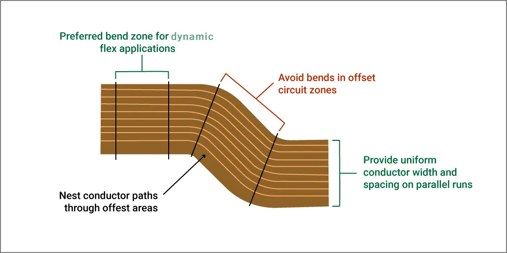
The foundation of DFA flex PCB lies in understanding material behaviors under deformation, where copper traces on polyimide films experience tensile and compressive stresses during bending. Engineers must model strain distribution using finite element analysis to predict failure points, ensuring traces run parallel to the bend axis rather than perpendicular to avoid necking. In rigid-flex constructions, the transition zone between rigid and flex areas demands precise layer alignment to prevent adhesive voids that could propagate cracks during flexure. Component leads and solder joints represent vulnerability points, as thermal expansion mismatches exacerbate cyclic loading in operational environments. DFA principles dictate that designs facilitate flat assembly, with post-process folding confined to designated bend zones.
Bending radius DFA emerges as a core principle, dictating the minimum curvature allowable without compromising integrity. Insufficient radius leads to conductor thinning on the outer bend surface, reducing current-carrying capacity and risking opens. Standards like IPC-2223 provide guidelines for bend radii based on copper thickness and substrate properties, typically scaling with material stack-up height. For dynamic flex applications, repeated bend cycles amplify fatigue, necessitating wider traces and annular ring reinforcements at vias. These principles extend to thermal management, where DFA avoids heat-trapping geometries that could warp flex sections during reflow soldering.
Adhesive selection flex represents another technical pillar, as bonding agents in rigid-flex must withstand peel forces while maintaining interlayer adhesion under flexure. Acrylic or epoxy adhesives exhibit varying peel strengths, influencing design tolerances for coverlay application. Poor selection results in delamination during assembly handling or environmental exposure, compromising signal integrity. Engineers evaluate adhesives for compliance with qualification tests, ensuring compatibility with lamination cycles and subsequent chemical processes.
Suggested Reading: Optimizing Product Design: An Engineer's Guide to Design for Assembly (DFA)
Practical Best Practices for Component Placement and Stress Minimization
Component placement flex strategies prioritize rigid sections for high-profile devices, relegating low-profile passives and fine-pitch ICs to stable flex tails. Keep-out zones around bend lines prevent placement within strain-relief distances, typically extending 2-3 times the component height perpendicular to the flex axis. This approach facilitates vacuum pick-up without substrate distortion and aligns with automated vision systems for fiducial recognition. In rigid-flex, hybrid placement sequences assemble rigid areas first, using temporary stiffeners on flex sections to mimic rigid behavior during SMT. Logical zoning reduces cross-contamination risks from flux residues migrating into flex folds.
Minimizing stress flex involves trace routing optimizations, such as teardrop pads to distribute shear forces and hatched ground planes to equalize strain. Vias in flex regions require staggered patterns to avoid barrel cracking under compression, while blind vias in rigid sections preserve flex integrity. Engineers incorporate strain gauges in prototypes to validate designs, correlating simulated stresses with empirical data. These practices enhance joint reliability, particularly for ball-grid arrays where underfill may be infeasible in flex areas.
Adhesive selection flex best practices emphasize shear and peel strength metrics, selecting modified epoxies for high-cycle applications and polyimides for thermal stability. Application thickness uniformity prevents stress risers, achieved through controlled lamination pressures. Compatibility testing ensures no outgassing affects nearby components during reflow, maintaining void-free bonds. In DFA rigid-flex PCB workflows, adhesive specs integrate with stack-up definitions, influencing overall board thickness and bend compliance.
Bending radius DFA guidelines recommend static radii of at least 10 times the flex stack thickness for single bends, scaling upward for dynamic use. Design files annotate nominal bend lines with radius callouts, guiding assembly fixturing. Overly tight radii necessitate coverlay reliefs to accommodate material elongation, preventing cracking at trace-coverlay interfaces. Integrating these into DFA checklists ensures manufacturability without compromising electrical spacing.
Related Reading: Constraint Management Techniques for Flexible and Rigid Flex PCBs
Challenges and Troubleshooting in DFA Implementation
Engineers often encounter warpage in rigid-flex during cooling post-lamination, distorting fiducials and impeding placement accuracy. Mitigation involves symmetric stack-ups and controlled cure cycles, verified through shadow moiré analysis. Another challenge arises in multi-bend flex tails, where cumulative strain exceeds material limits, addressed by segmented bend zones with relief slits. Troubleshooting solder joint cracks post-flexing requires cross-section microscopy, revealing underfill needs or lead compliance issues. DFA workflows incorporate design reviews at 30% and 90% completion to catch these early.
In high-reliability applications, IPC-A-610 criteria guide visual inspections, classifying defects by class to prioritize fixes. Thermal profiling during assembly simulates operational stresses, adjusting conveyor speeds for flex boards. These structured diagnostics maintain yield targets, fostering iterative improvements.
Conclusion
Implementing DFA in flex and rigid-flex PCB design demands a logical integration of mechanical, material, and process considerations to achieve robust assemblies. Key practices like strategic component placement flex, precise bending radius DFA, thoughtful adhesive selection flex, and proactive minimizing stress flex directly enhance reliability and efficiency. Adhering to standards such as IPC-2223 and IPC-A-610 ensures designs meet industry benchmarks without unnecessary complexity. Engineers benefit from early DFA adoption, reducing assembly risks and enabling innovative applications in constrained spaces. Ultimately, these principles transform potential failure modes into strengths, supporting scalable production.
FAQs
Q1: What role does bending radius DFA play in flex PCB assembly?
A1: Bending radius DFA ensures flex sections withstand folding without trace or solder damage by specifying minimum curvatures based on stack-up thickness. Engineers define keep-out zones and route traces parallel to bends to prevent fatigue during handling and use. This aligns with IPC-2223 guidelines, reduces stress, and improves yields while aiding fixturing for streamlined SMT processes.
Q2: How does component placement flex impact DFA rigid-flex PCB reliability?
A2: Component placement flex confines high-profile parts to rigid zones and uses low-profile devices on flex tails to avoid strain during bending. Keep-out margins around flex lines protect joints from peel forces, enhancing long-term durability. This zoning supports automated assembly, adheres to IPC-A-610 acceptance criteria, and reduces defects in DFA rigid-flex PCB designs.
Q3: Why is adhesive selection flex critical for minimizing stress?
A3: Adhesive selection flex prioritizes materials with high peel strength and thermal compatibility to securely bond rigid-flex layers. Incompatible adhesives can delaminate under cyclic bending and amplify stress concentrations. Selecting epoxies or acrylics qualified for flex applications ensures uniform bonds and directly contributes to stress minimization and overall DFA performance.
Q4: What are common best practices for DFA flex PCB in high-volume production?
A4: Best practices include flat assembly fixturing, robust fiducial placement for alignment, and trace reinforcements in bend areas. Annotate designs with bend radii and tolerances to guide operators, and run DFA checks before Gerber release. Combined with standard compliance, these steps optimize throughput and quality in DFA flex PCB manufacturing.
References
IPC-2223C — Section Qualification and Performance Specification for Flexible Printed Boards. IPC, 2019
IPC-6013DS — Qualification and Performance Specification for Flexible and Rigid-Flex Printed Boards. IPC, 2014
IPC-A-610H — Acceptability of Electronic Assemblies. IPC, 2019