Introduction
For electronic hobbyists, designing a printed circuit board (PCB) is an exciting step in bringing projects to life. However, one critical aspect often overlooked by beginners is thermal management. Poor thermal design can lead to overheating, reduced performance, and even failure of electrical circuits and electronic components. Understanding thermal conduction and the principles of thermodynamics is essential in electrical engineering and mechanical engineering to ensure reliability. This guide will walk you through the fundamentals of PCB thermal design, offering practical insights into managing heat dissipation effectively. Whether you are building a simple LED circuit or a complex microcontroller setup, mastering these concepts will enhance the durability and efficiency of your projects.
What Is PCB Thermal Design and Why It Matters
PCB thermal design focuses on managing heat generated by electronic components during operation. When current flows through electrical circuits, components like resistors, transistors, and integrated circuits produce heat due to power dissipation. If this heat is not dissipated properly, it can cause temperature rises beyond safe limits, leading to component degradation or system failure. Effective thermal design ensures that heat is transferred away from critical areas through conduction, convection, and radiation.
For hobbyists, the stakes are high because overheating can ruin a project or pose safety risks. Proper thermal management extends the lifespan of electronic components and maintains performance. It also prevents issues like thermal stress, which can warp boards or crack solder joints. By prioritizing thermal design, you create reliable and efficient circuits that perform consistently under various conditions.
Technical Principles of PCB Thermal Design
Heat Generation in Electrical Circuits
Heat in PCBs primarily comes from power dissipation in electronic components. When current passes through a resistor or a semiconductor, energy is converted into heat based on the formula for power, which is the product of voltage and current. Components with high power ratings, such as voltage regulators or power transistors, are often the main heat sources. Understanding where heat originates in your electrical circuits is the first step in addressing thermal challenges.
Modes of Heat Transfer
Heat transfer in types of PCBs occurs through three mechanisms. First, thermal conduction moves heat through materials like copper traces and the board substrate from hot to cooler areas. Second, convection transfers heat from the PCB surface to the surrounding air, often aided by airflow. Third, radiation emits heat as infrared energy, though this is less significant in typical hobbyist projects. For most designs, conduction is the primary focus, as it directly relates to material choices and layout.
Thermal Resistance and Junction Temperature
Thermal resistance measures how much a material or component resists heat flow. It is a critical concept in electrical engineering for predicting temperature rises. High thermal resistance means heat struggles to escape, increasing the junction temperature at component leads. Standards like JEDEC J-STD-020E provide guidelines for assessing moisture and reflow sensitivity, which tie into thermal behavior during assembly. Keeping junction temperatures within manufacturer-specified limits is vital for reliability.
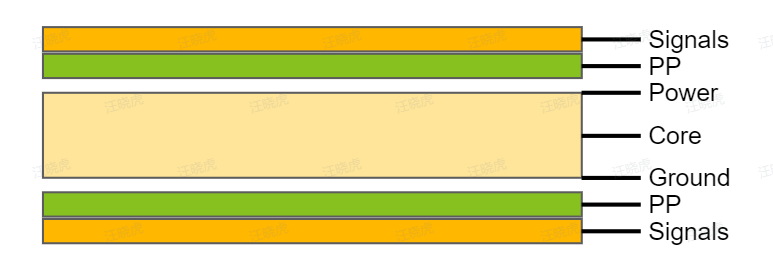
Impact of Board Materials on Thermal Conduction
The choice of PCB material significantly affects thermal conduction. Standard FR-4 boards, made of fiberglass and epoxy, have moderate thermal conductivity. For high heat applications, materials with better thermal properties, such as metal-core PCBs, may be considered. Copper layers also play a role, as thicker traces and planes conduct heat more effectively. Balancing cost and performance is key for hobbyists when selecting materials.
Practical Solutions for Effective Thermal Design
Optimize Component Placement
Place heat-generating electronic components strategically on the PCB. Position high-power components away from sensitive parts like microcontrollers or sensors to minimize thermal interference. Grouping components with similar thermal profiles can help manage heat distribution. Ensure adequate spacing to allow airflow for convection cooling, especially in enclosed projects. Thoughtful placement reduces hot spots and improves overall thermal performance.
Use Thermal Vias and Copper Planes
Thermal vias are small holes filled or plated with conductive material, connecting copper layers to transfer heat away from components. Place them under or near heat sources to enhance conduction to other layers or a heat sink. Large copper planes on the PCB surface or inner layers act as heat spreaders, distributing thermal energy evenly. These techniques are simple yet effective for hobbyists working on compact designs.
Suggested Reading: Mastering Thermal Vias: Essential Heat Management for High-Power PCBs
Select Appropriate Trace Widths
Trace width impacts both current capacity and heat dissipation in electrical circuits. Narrow traces have higher resistance, leading to increased heat generation. Use wider traces for high-current paths to reduce resistance and improve thermal conduction. Standards like IPC-2221 provide guidelines for trace width based on current and temperature rise, ensuring safe operation. This is particularly important for power supply lines in your projects.
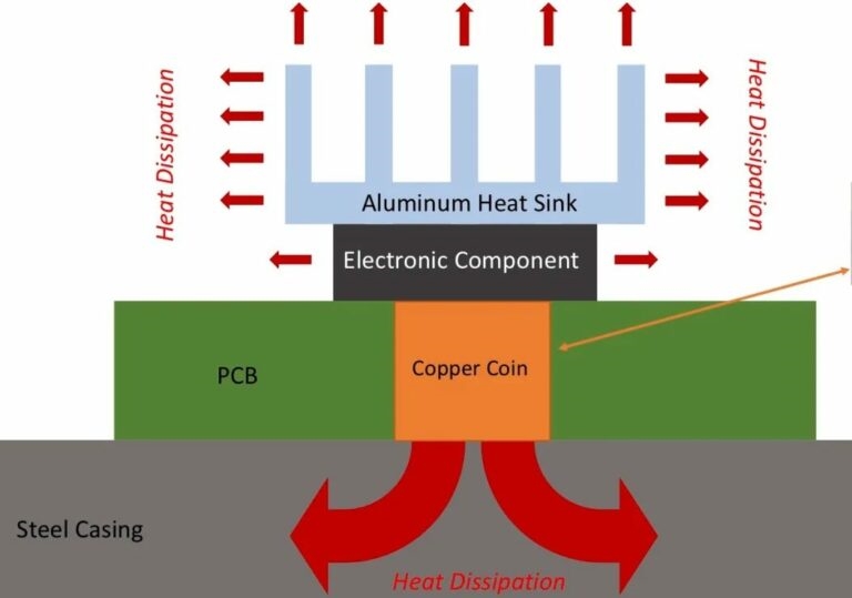
Incorporate Heat Sinks and Cooling Methods
Heat sinks are passive cooling devices that absorb and dissipate heat from components. Attach them to high-power components like voltage regulators using thermal paste for better contact. For active cooling, small fans can enhance convection in enclosed setups. While heat sinks add bulk, they are often necessary for managing significant heat loads in hobbyist projects involving power electronics.
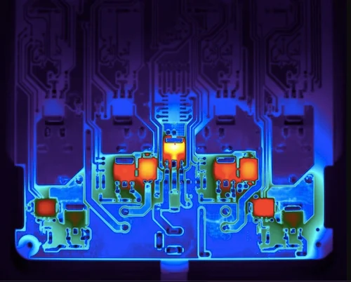
Simulate and Test Thermal Performance
Before finalizing a design, simulate the thermal behavior using software tools that model heat distribution. These simulations predict hot spots and help refine layouts. After assembly, test the PCB under operating conditions using a thermal camera or temperature probes to verify performance. Standards like IPC-9701 offer methods for thermal cycling testing to assess reliability. Testing ensures your design handles real-world thermal loads.
Common Thermal Design Challenges for Hobbyists
Hobbyists often face unique challenges in thermal design due to limited resources and experience. One common issue is underestimating heat generation in compact designs, leading to overcrowded boards with insufficient cooling. Another is neglecting the impact of ambient temperature, especially in outdoor projects where conditions vary. Using low-cost materials with poor thermal conductivity can also exacerbate problems. Addressing these challenges requires careful planning, adherence to basic principles of thermodynamics, and iterative testing.
For example, a hobbyist building a motor driver circuit might notice erratic behavior due to overheating of power transistors. By spacing components further apart, adding thermal vias, and attaching a small heat sink, the issue can be mitigated. Learning from such scenarios helps build intuition for thermal design in electrical engineering projects.
Conclusion
Mastering PCB thermal design is a fundamental skill for electronic hobbyists aiming to create reliable and efficient projects. By understanding heat generation in electrical circuits and applying principles of thermal conduction and thermodynamics, you can prevent overheating and extend the lifespan of electronic components. Practical steps like optimizing component placement, using thermal vias, and incorporating cooling solutions make a significant difference. As you gain experience in electrical engineering and mechanical engineering, these techniques will become second nature, ensuring your designs perform consistently. Start small, test often, and prioritize thermal management in every project for the best results.
FAQs
Q1: How does thermal conduction affect PCB performance in electrical circuits?
A1: Thermal conduction determines how effectively heat moves away from electronic components in electrical circuits. Poor conduction leads to hot spots, raising junction temperatures and risking component failure. Using materials with good thermal conductivity, like copper, and adding thermal vias can improve heat dissipation. Following guidelines from standards like IPC-2221 helps ensure safe temperature limits, maintaining performance and reliability in your hobbyist projects.
Q2: Why is thermodynamics important for electronic components on a PCB?
A2: Thermodynamics governs heat transfer and energy flow, critical for protecting electronic components on a PCB. Heat from power dissipation can degrade components if not managed properly. Understanding heat transfer modes, such as conduction and convection, allows hobbyists to design layouts that prevent overheating. This ensures components operate within safe temperature ranges, preserving functionality and extending the lifespan of your circuits.
Q3: What role does electrical engineering play in PCB thermal design?
A3: Electrical engineering provides the foundation for understanding power dissipation and heat generation in PCB circuits. It guides the selection of components and trace widths to minimize resistance and heat buildup. Engineers use standards like IPC-9701 to test thermal performance under load. For hobbyists, applying these principles means designing circuits that balance electrical efficiency with thermal safety, avoiding failures due to overheating.
Q4: How can mechanical engineering principles improve PCB cooling?
A4: Mechanical engineering contributes to PCB cooling by optimizing physical layouts and cooling structures. Techniques like spacing components for airflow and attaching heat sinks rely on mechanical design concepts. It also informs enclosure designs to enhance convection. Hobbyists can apply these ideas to manage heat in compact projects, ensuring structural integrity and effective cooling without compromising the board’s functionality.
References
IPC-2221 — Generic Standard on Printed Board Design. IPC, Current Version.
IPC-9701 — Performance Test Methods and Qualification Requirements for Surface Mount Solder Attachments. IPC, Current Version.
JEDEC J-STD-020E — Moisture/Reflow Sensitivity Classification for Nonhermetic Surface Mount Devices. JEDEC, 2014.


