Introduction
For electronic hobbyists, designing and building printed circuit boards (PCBs) is an exciting journey into the world of electronics. A critical aspect of PCB design is selecting the appropriate copper thickness. This choice impacts the performance, durability, and cost of your project. Copper thickness determines how much current a board can carry, its heat dissipation capabilities, and its mechanical strength. Understanding copper properties and thickness requirements is essential for hobby applications, whether you are crafting a simple LED circuit or a complex microcontroller setup. This guide provides a detailed look into copper thickness in PCBs, offering practical advice and material insights tailored for hobbyists. By grasping these concepts, you can ensure your designs are both functional and reliable for various hobbyist PCB projects.
What Is Copper Thickness in PCBs and Why It Matters
Copper thickness in PCBs refers to the amount of copper foil laminated onto the board's substrate, typically measured in ounces per square foot (oz/ft2). This unit indicates the weight of copper spread over a square foot, translating to a specific thickness. For instance, 1 oz/ft2 corresponds to approximately 1.4 mils or 35 micrometers. This measurement is crucial as it directly affects the board's ability to handle electrical current and heat.
For hobbyists, selecting the right copper thickness is vital for ensuring project success. Thinner copper layers are cheaper and easier to etch at home, making them suitable for low power applications like simple sensors. Thicker copper, however, is necessary for projects requiring higher current, such as power supplies or motor controllers, to prevent overheating and ensure reliability. Understanding thickness requirements helps hobbyists avoid issues like trace burning or signal interference, balancing cost with performance in hobby applications.
Technical Principles of Copper Thickness in PCBs
Copper serves as the conductive layer in PCBs, forming traces, pads, and vias that carry electrical signals. Its thickness influences several key properties, including electrical conductivity, thermal management, and mechanical strength. Let's explore these principles to understand copper's role in hobbyist PCB designs.
Electrical Conductivity and Current Carrying Capacity
The primary function of copper in a PCB is to conduct electricity. Thicker copper layers can carry more current without excessive voltage drop or heat generation. According to industry standards like IPC-2221B, Generic Standard on Printed Board Design, the current carrying capacity of a trace depends on its width, length, and copper thickness. For hobbyists, this means that a 1 oz copper layer might suffice for low current projects, while a 2 oz layer could be necessary for moderate power needs.
Related Reading: How to Choose Between 1oz and 2oz Copper PCBs For Your Project
Thermal Management
Copper also acts as a heat dissipator. Thicker layers spread heat more effectively, reducing the risk of hotspots that could damage components. In hobby applications involving high power LEDs or amplifiers, a thicker copper layer helps maintain thermal stability, ensuring longevity of the circuit.
Mechanical Strength
Copper thickness contributes to the structural integrity of a PCB. Thicker copper provides better resistance to bending and mechanical stress, which is useful for hobbyists creating durable prototypes. However, excessively thick copper can increase manufacturing complexity and cost, which might not be ideal for simple hobbyist projects.
Copper Properties Relevant to Hobbyist PCB Design
Understanding the material properties of copper is essential for selecting the right thickness in PCB design. Copper is chosen for its excellent electrical and thermal conductivity, but other characteristics also play a role in hobby applications.
Electrical Conductivity
Copper has one of the highest electrical conductivities among metals, making it ideal for PCB traces. Its resistivity is low, allowing efficient current flow with minimal loss. This property ensures that even thin copper layers can handle small currents effectively in hobbyist projects.
Thermal Conductivity
With high thermal conductivity, copper efficiently transfers heat away from components. This is critical for hobby applications where components like power transistors generate significant heat. Thicker copper enhances this capability, protecting sensitive parts from thermal damage.
Ductility and Workability
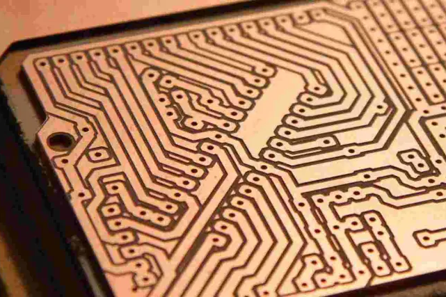
Copper is ductile, meaning it can be easily formed into thin foils and etched into precise patterns. For hobbyists using DIY etching methods, this property makes copper manageable, even with basic tools. However, care must be taken as thinner layers are more prone to damage during handling.
Corrosion Resistance
Copper naturally forms a protective oxide layer, offering some resistance to corrosion. While not as corrosion resistant as other metals, this property is sufficient for most indoor hobby applications. For outdoor projects, hobbyists should consider protective coatings to enhance durability.
Thickness Requirements for Hobbyist Applications
Selecting the appropriate copper thickness for hobbyist PCB projects involves balancing performance needs with practical constraints like cost and manufacturing ease. Below are common thickness options and their suitability for various hobby applications, guided by standards such as IPC-6012E, Qualification and Performance Specification for Rigid Printed Boards.
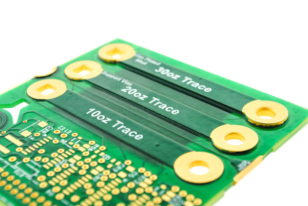
Standard Thickness Options
- 0.5 oz/ft2 (17.5 micrometers): Lightweight and cost effective, ideal for low power circuits like simple sensors or logic circuits. It is easy to etch but limited in current capacity.
- 1 oz/ft2 (35 micrometers): The most common choice for hobbyist PCBs, suitable for general purpose projects including microcontrollers and small power supplies. It offers a good balance of cost and performance.
- 2 oz/ft2 (70 micrometers): Used for higher current applications such as motor drivers or LED arrays. It provides better thermal management but is harder to etch manually.
- 3 oz/ft2 and above (105 micrometers+): Reserved for high power applications like large power converters. These are less common in hobbyist settings due to cost and etching challenges.
Related Reading: The Ultimate Guide to 2oz Copper PCB Design for Beginners
Application Based Recommendations
For hobbyists, most projects fall within the 1 oz to 2 oz range. A basic LED blinking circuit can function well with 1 oz copper, ensuring low cost and ease of production. However, if you are building a drone motor controller, opting for 2 oz copper helps manage the higher currents and heat generated. Always consider the current requirements and thermal load of your design when choosing thickness.
Practical Tips for Choosing Copper Thickness in Hobbyist PCB Design
Selecting the right copper thickness for your hobbyist PCB involves practical considerations beyond just technical specifications. Here are actionable tips to guide your decision making process, ensuring your projects are both effective and feasible.
Assess Current and Power Needs
Start by calculating the expected current flow through your PCB traces. Use guidelines from IPC-2221B to determine the minimum trace width and copper thickness needed for safe operation. For low power hobby applications, 1 oz copper often suffices, but increase to 2 oz for currents exceeding a few amperes.
Consider Manufacturing Capabilities
If you are etching PCBs at home, thinner copper layers like 0.5 oz or 1 oz are easier to handle with basic chemicals and tools. Thicker layers require more precise control during etching, which might be challenging without professional equipment. Evaluate your setup before deciding on thickness.
Balance Cost with Performance
Thicker copper increases material and manufacturing costs. For hobbyists on a budget, start with 1 oz copper for most projects. Reserve 2 oz or higher for specific high power needs, ensuring you are not overpaying for unnecessary thickness.
Plan for Thermal Management
If your project involves heat generating components, thicker copper can help dissipate heat. Alternatively, design wider traces or add thermal vias to improve heat distribution without increasing copper thickness. This approach works well for hobby applications with limited budgets.
Troubleshooting Common Issues with Copper Thickness
Hobbyists often encounter challenges related to copper thickness during PCB design and assembly. Addressing these issues early can save time and resources. Below are common problems and solutions tailored for hobby applications.
Overheating Traces
If traces overheat, it indicates insufficient copper thickness or trace width for the current load. Recalculate using IPC-2221B guidelines and consider upgrading to a thicker copper layer or widening traces. Adding heat sinks near critical areas can also help.
Difficulty in Etching
Thicker copper takes longer to etch and may result in uneven traces if not done carefully. For home etching, stick to 1 oz copper or use pre fabricated boards for thicker layers. Ensure proper etchant concentration and timing to avoid under or over etching.
Mechanical Damage
Thin copper layers are prone to tearing or peeling during handling. Use gentle techniques when soldering or assembling components. If mechanical strength is a concern, consider a slightly thicker copper layer for added durability in hobbyist PCB designs.
Conclusion
Copper thickness plays a pivotal role in the success of hobbyist PCB projects. By understanding copper properties, thickness requirements, and their impact on electrical and thermal performance, hobbyists can make informed decisions for their designs. Whether you are working on a simple circuit or a more demanding application, selecting the right copper thickness ensures reliability and efficiency. Use this material guide to assess your project needs, apply practical tips, and troubleshoot issues effectively. With these insights, you can confidently tackle hobby applications, creating PCBs that meet both functional and budgetary goals.
FAQs
Q1: What is the best copper thickness for a hobbyist PCB project?
A1: For most hobbyist PCB projects, 1 oz/ft2 copper thickness is ideal. It handles low to moderate currents effectively, is cost friendly, and easy to etch at home. If your project involves higher currents, like motor controllers, consider 2 oz/ft2 for better performance. Always match thickness to your current and thermal needs using industry standards like IPC-2221B.
Q2: How do copper properties affect hobby applications?
A2: Copper properties like high electrical and thermal conductivity are crucial for hobby applications. They ensure efficient current flow and heat dissipation, protecting components in projects like LED circuits or amplifiers. Its ductility also aids in easy etching for DIY hobbyists. Understanding these traits helps in selecting appropriate materials for reliable performance.
Q3: What are the thickness requirements for high power hobbyist designs?
A3: High power hobbyist designs, such as power supplies or motor drivers, often require 2 oz/ft2 or thicker copper to manage increased current and heat. Refer to IPC-6012E for performance specifications. Thicker copper prevents overheating and trace damage, ensuring durability. Assess your project's power needs to choose the right thickness.
Q4: How can I avoid overheating in hobbyist PCB projects?
A4: To prevent overheating in hobbyist PCB projects, select an appropriate copper thickness, typically 1 to 2 oz/ft2, based on current load. Use wider traces and add thermal vias for better heat distribution. Following IPC-2221B guidelines helps calculate safe limits. Ensure proper component placement to minimize thermal stress during operation.
References
IPC-2221B — Generic Standard on Printed Board Design. IPC, 2012.
IPC-6012E — Qualification and Performance Specification for Rigid Printed Boards. IPC, 2020.


