Introduction
Hybrid stack-up design in RF laminate PCBs represents a critical approach for electrical engineers aiming to balance performance, reliability, and cost in high-frequency applications. By combining different materials, such as FR4 and specialized RF laminates, engineers can optimize electrical properties while addressing thermal and mechanical challenges like CTE matching. This article explores advanced techniques for designing a hybrid stack-up PCB, focusing on RF PCB FR4 combinations, multilayer PCB design, and cost-effective solutions. The goal is to provide actionable insights into achieving signal integrity and structural stability in demanding environments. Whether working on telecommunications, aerospace, or automotive systems, understanding these methods can significantly enhance PCB performance. Let’s delve into the principles, practices, and considerations for mastering hybrid stack-up design.
What Is Hybrid Stack-Up PCB Design and Why It Matters
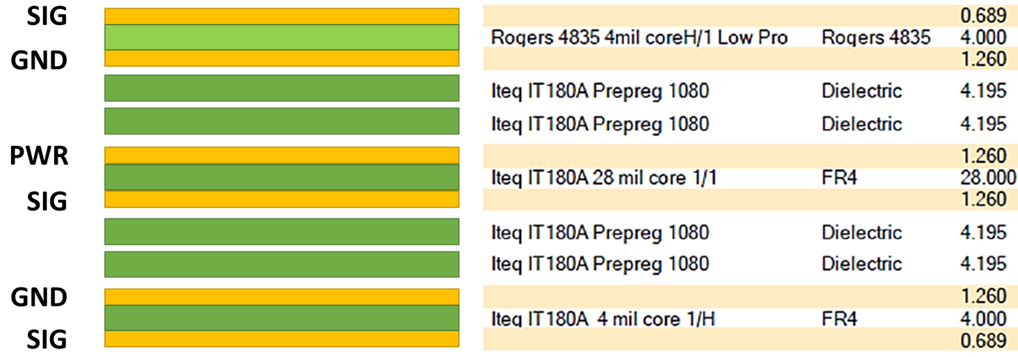
A hybrid stack-up PCB refers to a multilayer board constructed using a combination of different dielectric materials tailored to specific performance needs. In RF applications, this often involves pairing cost-effective materials like FR4 with high-frequency laminates that offer low dielectric loss and stable electrical properties. The significance of hybrid stack-up design lies in its ability to meet the stringent requirements of RF systems, where signal integrity, impedance control, and thermal management are paramount.
The primary advantage of a hybrid stack-up PCB is cost efficiency. High-frequency laminates are expensive, so using them only in critical layers while employing FR4 in others reduces overall expenses. Additionally, this approach allows engineers to address CTE matching challenges, preventing warpage and delamination during thermal cycling. For industries relying on multilayer PCB design, such as wireless communication and radar systems, hybrid stack-ups ensure reliable performance without prohibitive costs. Properly executed designs mitigate signal loss and crosstalk, making them indispensable for modern electronics.
Technical Principles of Hybrid Stack-Up Design in RF PCBs
Understanding the technical foundations of hybrid stack-up design is essential for optimizing RF PCB FR4 combinations. The key lies in material selection and layer arrangement to balance electrical, thermal, and mechanical properties.
Material Properties and Compatibility
In RF applications, dielectric constant and loss tangent are critical parameters. High-frequency laminates typically have a lower dielectric constant and loss tangent compared to FR4, ensuring minimal signal attenuation at gigahertz frequencies. However, FR4 remains a staple in non-critical layers due to its affordability and mechanical strength. Combining these materials requires careful consideration of their compatibility during manufacturing processes like lamination, as outlined in standards such as IPC-6012E.
CTE Matching in PCB Design
Coefficient of Thermal Expansion (CTE) matching is a cornerstone of reliable hybrid stack-up design. Mismatched CTE values between layers can lead to stress, warpage, or delamination during temperature fluctuations. For instance, FR4 and RF laminates often differ in CTE along the X, Y, and Z axes. Engineers must select materials with similar CTE values or use symmetrical stack-ups to minimize thermal stress. Adhering to guidelines in IPC-A-600K helps ensure acceptable board flatness and structural integrity.
Impedance Control and Signal Integrity
Maintaining consistent impedance across layers is vital in RF PCB design. Variations in dielectric properties between FR4 and RF laminates can disrupt signal paths, leading to reflections and loss. Engineers must calculate trace widths and spacing based on the dielectric constant of each layer, often using simulation tools to predict performance. Multilayer PCB design further complicates this, as internal layers may carry high-speed signals requiring precise impedance matching.
Related Reading: Dielectric Thickness and Impedance: A PCB Design Essential
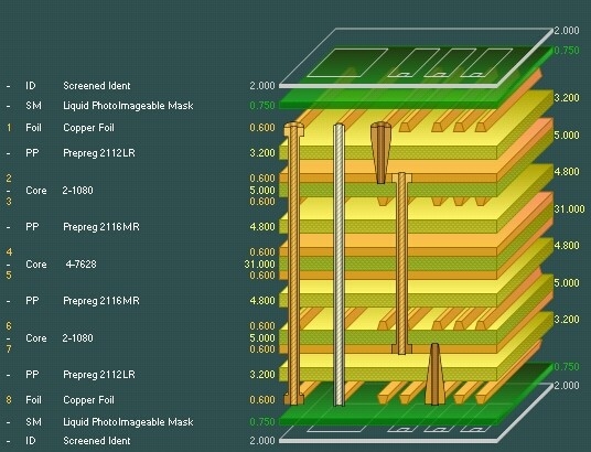
Layer Arrangement Strategies
Strategic layer placement enhances performance in a hybrid stack-up PCB. RF signal layers are typically positioned near high-frequency laminates to leverage their low-loss properties, while power and ground planes use FR4 for cost savings. Symmetrical arrangements also help balance mechanical stress, reducing the risk of bending or twisting during thermal cycles.
Practical Solutions for Cost-Effective RF PCB Design
Creating a cost-effective RF PCB without compromising performance involves several actionable strategies. These solutions cater to electrical engineers seeking reliable and budget-friendly designs.
Optimizing Material Usage
To achieve a cost-effective RF PCB, limit the use of expensive high-frequency laminates to layers handling critical signals. FR4 can suffice for power distribution and non-RF layers in a multilayer PCB design. This selective material approach reduces expenses while maintaining essential electrical performance. Consulting standards like IPC-6012E ensures that material choices align with manufacturing capabilities and quality requirements.
Enhancing CTE Matching Techniques
Effective CTE matching in PCB design starts with selecting materials with comparable thermal expansion properties. When differences exist, engineers can use prepreg layers with adjusted resin content to buffer stress between dissimilar materials. Additionally, maintaining symmetry in the stack-up by mirroring material types and thicknesses across the board’s centerline minimizes warpage risks. Such practices align with acceptability criteria in IPC-A-600K.
Leveraging Multilayer Design Efficiency
Multilayer PCB design offers opportunities to integrate complex circuits into a compact footprint. By carefully planning layer functions, engineers can dedicate specific layers to RF signals, grounding, and power distribution. This segregation reduces interference and enhances signal integrity. Proper via placement and routing also play a role in minimizing signal loss, especially in hybrid stack-up PCBs with mixed materials.
Simulation and Testing for Reliability
Before fabrication, simulating the hybrid stack-up design helps identify potential issues like impedance mismatches or thermal stress points. Post-manufacturing testing, including thermal cycling and electrical performance evaluation, ensures the board meets design specifications. Following testing protocols in standards such as JEDEC J-STD-020E can validate the board’s resilience to environmental stressors.
Troubleshooting Common Challenges in Hybrid Stack-Up Design
Hybrid stack-up PCBs, while advantageous, present unique challenges that electrical engineers must address to ensure reliability and performance.
Managing Warpage and Delamination
Warpage often results from uneven thermal expansion in RF PCB FR4 combinations. To mitigate this, ensure balanced copper distribution across layers and adhere to symmetrical stack-up principles. Delamination, another concern, can be prevented by selecting compatible prepreg and core materials during lamination, following guidelines in IPC-6012E for process control.
Addressing Signal Integrity Issues
Signal degradation in hybrid stack-ups often stems from dielectric mismatches or improper layer transitions. Engineers should maintain consistent dielectric properties near RF traces and use ground planes to shield signals from interference. Careful via design also prevents signal discontinuities in multilayer PCB layouts.
Cost Management Without Quality Loss
Balancing cost and quality in a cost-effective RF PCB requires strategic compromises. Opt for fewer layers of high-frequency materials and prioritize their placement in signal-critical areas. Bulk purchasing of standard materials like FR4 for non-critical layers can further reduce expenses without affecting performance.
Related Reading: PCB Material Selection: Balancing Thermal Performance and Cost
Conclusion
Hybrid stack-up design in RF laminate PCBs offers a powerful solution for electrical engineers seeking to optimize performance and cost in high-frequency applications. By mastering material selection, CTE matching, and multilayer PCB design, engineers can create reliable boards that meet the demands of modern electronics. Techniques like strategic layer arrangement and simulation ensure signal integrity and mechanical stability, while cost-effective approaches make these designs accessible for various projects. Applying industry standards and thorough testing further guarantees success in implementing a hybrid stack-up PCB. With these advanced methods, achieving excellence in RF PCB design becomes a practical reality.
FAQs
Q1: What are the benefits of using a hybrid stack-up PCB in RF applications?
A1: A hybrid stack-up PCB combines materials like FR4 and high-frequency laminates to balance cost and performance. This approach reduces expenses by limiting expensive materials to critical layers while maintaining signal integrity in RF systems. It also allows tailored thermal and mechanical properties, enhancing reliability in demanding environments as per standards like IPC-6012E.
Q2: How does CTE matching impact PCB reliability in multilayer PCB design?
A2: CTE matching in PCB design prevents stress and warpage caused by thermal expansion differences between materials. In multilayer PCB design, mismatched CTE can lead to delamination or board failure during temperature changes. Selecting compatible materials and symmetrical stack-ups, aligned with IPC-A-600K, ensures structural stability and long-term reliability.
Q3: What strategies make a cost-effective RF PCB possible without quality loss?
A3: Creating a cost-effective RF PCB involves using high-frequency laminates only in critical signal layers and FR4 elsewhere. Symmetrical stack-ups and optimized layer counts reduce material and manufacturing costs. Following guidelines in IPC-6012E ensures quality is maintained, allowing engineers to balance budget constraints with performance needs.
Q4: How can engineers ensure signal integrity in RF PCB FR4 combinations?
A4: Signal integrity in RF PCB FR4 combinations requires consistent dielectric properties near signal traces and proper grounding. Using ground planes and precise impedance calculations minimizes loss and interference. Simulation before fabrication and testing per JEDEC J-STD-020E standards help validate performance in hybrid designs.
References
IPC-6012E — Qualification and Performance Specification for Rigid Printed Boards. IPC, 2020.
IPC-A-600K — Acceptability of Printed Boards. IPC, 2020.
JEDEC J-STD-020E — Moisture/Reflow Sensitivity Classification. JEDEC, 2014.


