Introduction
Grounding strategies play a pivotal role in the design of printed circuit boards (PCBs) for electric vehicle (EV) battery management systems (BMS). These systems monitor and control high-voltage battery packs, ensuring safety, efficiency, and longevity. Poor grounding can lead to noise interference, ground loops, and safety hazards, compromising performance. Effective grounding techniques, such as implementing a solid ground plane, utilizing star grounding, or applying single-point grounding, are essential to minimize impedance and enhance signal integrity. This article explores the best practices for grounding in EV BMS PCB designs, focusing on methods like multi-point grounding, chassis ground integration, and impedance control. Aimed at electrical engineers, this guide provides actionable insights to optimize designs for reliability and safety in high-power environments.
Why Grounding Matters in EV Battery Management Systems
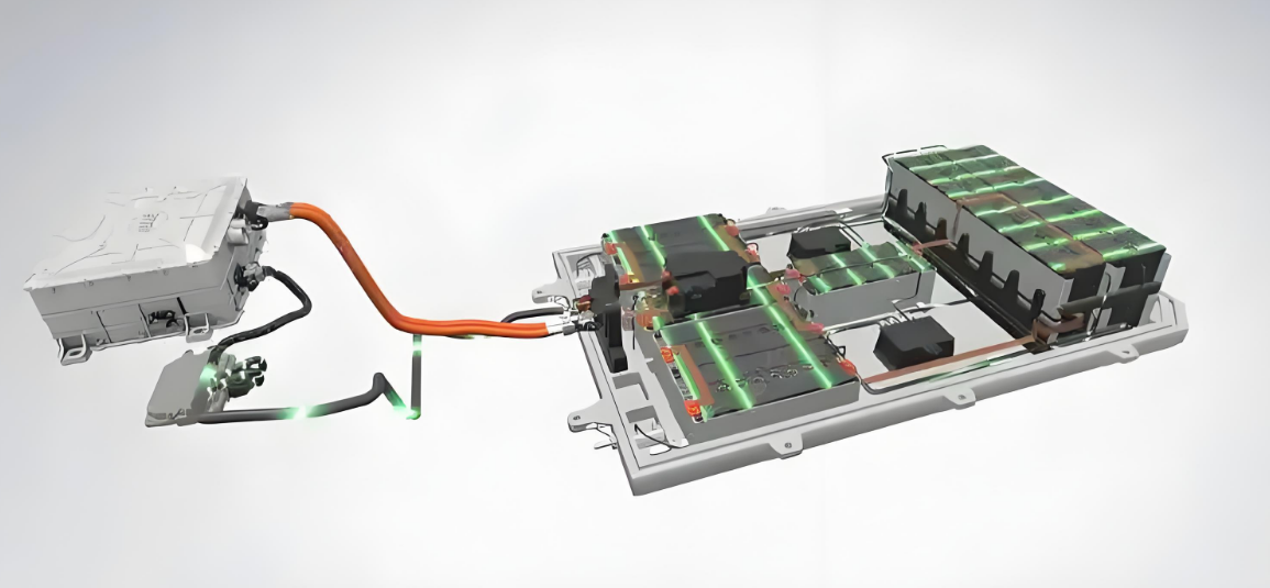
Grounding in PCB design establishes a reference point for electrical signals and provides a path for fault currents to ensure safety. In EV battery management systems, grounding is critical due to the high voltages and currents involved, often exceeding 400 volts. Improper grounding can result in electromagnetic interference (EMI), signal distortion, and potential safety risks like electric shocks or fires. Techniques such as earth ground connections and safety ground implementations protect both the system and users. Beyond safety, grounding impacts system performance by reducing noise through methods like ground plane design and preventing ground loops. For EV BMS, where precision in voltage and current monitoring is vital, grounding directly influences data accuracy and system stability.
Suggested Reading: Key Features of Battery Management Systems (BMS)
Technical Principles of Grounding in PCB Design
Understanding Ground Types and Their Roles
Grounding in PCB design involves different types, each serving a unique purpose. A ground plane is a large conductive area on the PCB acting as a common return path for currents, minimizing impedance and noise. Chassis ground connects the PCB to the vehicle's metal frame, providing a safety ground to divert fault currents. Earth ground links the system to the physical earth, often through the chassis, ensuring a stable reference. Safety ground focuses on protecting users by directing hazardous currents away from accessible parts, aligning with standards like IEC 60950-1:2005 for electrical safety.
Grounding Configurations: Single-Point, Multi-Point, and Star Grounding
Grounding configurations determine how different circuit sections connect to the ground reference. Single-point grounding connects all ground points to a single node, reducing the risk of ground loops, which occur when multiple ground paths create unwanted current flow. This method suits low-frequency circuits in EV BMS for analog sensor signals. Multi-point grounding, connecting grounds at multiple locations, is effective for high-frequency designs, ensuring low impedance across the board. Star grounding, a subset of single-point grounding, routes all ground connections to a central point in a star pattern, minimizing interference in mixed-signal designs with digital and analog components.
Ground Loops and Impedance Control Challenges
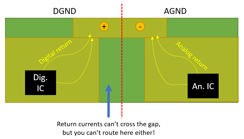
Ground loops are a common issue in complex systems like EV BMS, where multiple ground paths can induce noise from circulating currents. This affects sensor accuracy and communication signals. Impedance control is crucial to mitigate such issues, ensuring ground paths have minimal resistance and inductance. A well-designed ground plane reduces impedance by providing a low-resistance path. Separating analog and digital grounds, then connecting them at a single point, further prevents noise coupling. Standards like IPC-2221B:2012 for generic PCB design emphasize maintaining short, direct ground paths to control impedance effectively.
Best Practices for Grounding in EV Battery Management PCB Designs
Implement a Robust Ground Plane
A continuous ground plane is fundamental for EV BMS PCBs. It provides a low-impedance path for return currents, reducing EMI and signal crosstalk. Place the ground plane on an inner layer in the multilayer circuit board to maximize coverage and avoid interruptions from vias or components. Ensure high-current paths, such as those near battery connectors, have direct access to the ground plane to handle fault currents safely. Following guidelines from IPC-6012E:2020 for rigid PCB performance, maintain consistent copper thickness to support current demands without thermal issues.
Choose the Right Grounding Configuration
Selecting between single-point grounding and multi-point grounding depends on the circuit's frequency and layout. For low-frequency analog signals in battery voltage monitoring, single-point grounding or star grounding minimizes noise by avoiding multiple return paths. In contrast, multi-point grounding suits high-frequency digital sections, like communication interfaces, by reducing impedance across distributed points. Evaluate the PCB layout early to determine the optimal configuration, ensuring compliance with IEC 61000-4-2:2008 for electromagnetic compatibility in grounding design.
Integrate Chassis Ground and Safety Ground
Connecting the PCB ground to the chassis ground is essential for safety in EV systems. This ensures fault currents are directed to the vehicle's metal frame, protecting users and components. Use dedicated mounting holes or connectors for chassis ground, avoiding reliance on signal grounds for safety functions. Safety ground connections must adhere to standards like IEC 60364-5-54:2011 for protective earthing, ensuring reliable fault current dissipation. Test these connections for low resistance to confirm effectiveness during fault conditions.
Minimize Ground Loops Through Layout Design
Preventing ground loops requires careful layout planning. Route ground connections to avoid creating multiple paths between circuit sections. For mixed-signal designs, separate analog and digital ground planes, connecting them at a single point near the power supply entry. This approach reduces noise coupling, as recommended by IPC-A-600K:2020 for PCB acceptability. Use simulation tools to identify potential loop formations during the design phase, adjusting traces to maintain a clean grounding scheme.
Prioritize Impedance Control in High-Current Paths
Impedance control is vital for high-current paths in EV BMS designs. Minimize trace lengths and widen ground connections near battery terminals to handle large currents without voltage drops. Incorporate multiple vias to connect ground planes across layers, reducing inductance. Adhering to IPC-2221B:2012, calculate trace widths based on current ratings to ensure thermal stability and low impedance. Regularly review layer stackups to optimize ground plane proximity to signal layers for better return path efficiency.
Separate Analog and Digital Grounds
In EV BMS, analog circuits for sensor readings and digital circuits for data processing often coexist. Noise from digital switching can interfere with analog precision. Maintain separate ground planes for these domains, connecting them at a single point to avoid ground loops. This practice aligns with best practices in mixed-signal design, ensuring clean signal references. Place this connection point near the power supply to centralize return currents effectively.
Troubleshooting Grounding Issues in EV BMS Designs
Grounding issues often manifest as noise in sensor readings or erratic communication signals in EV BMS. Start troubleshooting by measuring voltage differences between ground points using a high-precision multimeter. Significant variations indicate potential ground loops or high impedance paths. Inspect the PCB layout for unintended ground connections or long return paths, correcting them by rerouting traces or adding vias. Verify chassis ground connections for low resistance, ensuring they meet safety standards like IEC 60364-5-54:2011. Simulate the design under load conditions to identify EMI sources, adjusting the ground plane or shielding as needed.
Conclusion
Effective grounding strategies are indispensable for reliable and safe EV battery management PCB designs. Implementing a robust ground plane, choosing between single-point grounding or multi-point grounding, and integrating chassis ground connections ensure system stability and user safety. Techniques like star grounding and impedance control further enhance performance by minimizing noise and ground loops. By adhering to industry standards such as IPC-6012E:2020 and IEC 60364-5-54:2011, engineers can design BMS PCBs that meet the demanding requirements of electric vehicles. Careful planning and simulation during the design phase are key to avoiding common grounding pitfalls.
FAQs
Q1: How does a ground plane improve EV BMS PCB performance?
A1: A ground plane provides a low-impedance path for return currents, reducing electromagnetic interference and signal noise in EV battery management systems. It stabilizes voltage references, ensuring accurate sensor readings and reliable communication. By covering a large PCB area, it minimizes impedance, enhancing overall system performance in high-power environments.
Q2: What is the difference between single-point grounding and multi-point grounding?
A2: Single-point grounding connects all ground paths to one node, ideal for low-frequency circuits to prevent ground loops. Multi-point grounding uses multiple connections, suitable for high-frequency designs to maintain low impedance across the PCB. Choosing between them depends on the specific EV BMS circuit requirements and frequency characteristics.
Q3: Why is chassis ground critical for safety in EV designs?
A3: Chassis ground connects the PCB to the vehicle's metal frame, directing fault currents away from users and components. It acts as a safety ground, preventing electric shocks and ensuring compliance with standards like IEC 60364-5-54:2011. This connection is vital for protecting EV systems under fault conditions.
Q4: How can ground loops be avoided in EV BMS PCB layouts?
A4: Ground loops can be avoided by using star grounding or single-point grounding to ensure a single return path. Separate analog and digital grounds, connecting them at one point near the power supply. Review layouts to eliminate multiple ground paths, adhering to guidelines in IPC-A-600K:2020 for optimal design.
References
IPC-6012E:2020 — Qualification and Performance Specification for Rigid Printed Boards. IPC, 2020.
IPC-A-600K:2020 — Acceptability of Printed Boards. IPC, 2020.
IPC-2221B:2012 — Generic Standard on Printed Board Design. IPC, 2012.
IEC 60950-1:2005 — Information Technology Equipment - Safety - Part 1: General Requirements. IEC, 2005.
IEC 60364-5-54:2011 — Low-Voltage Electrical Installations - Part 5-54: Selection and Erection of Electrical Equipment - Earthing Arrangements and Protective Conductors. IEC, 2011.
IEC 61000-4-2:2008 — Electromagnetic Compatibility (EMC) - Part 4-2: Testing and Measurement Techniques - Electrostatic Discharge Immunity Test. IEC, 2008.


