Why Invest in a DIY PCB Diagnostic Station?
Printed Circuit Boards (PCBs) form the fundamental hardware for nearly all modern electronic devices, making thorough testing an indispensable step before their deployment. While professional-grade testing equipment often carries a hefty price tag, potentially reaching thousands of dollars, such an investment is often impractical for hobbyists or small-scale prototyping endeavors. Crafting your own DIY PCB testing setup provides a significantly more affordable alternative. This approach empowers you to efficiently troubleshoot common issues such as short circuits, open traces, or malfunctioning components, leveraging readily available tools or those easily acquired. Furthermore, designing your own diagnostic station offers unparalleled flexibility for customization, allowing you to tailor the setup precisely to the unique demands of your projects.
Essential Components for Your Homemade PCB Tester
Before embarking on the construction of a PCB test jig, it’s crucial to assemble the necessary tools and components. Most of these items are budget-friendly and widely accessible, making this project an economical diagnostic solution. Here’s a detailed list of what you'll need:
Core Equipment
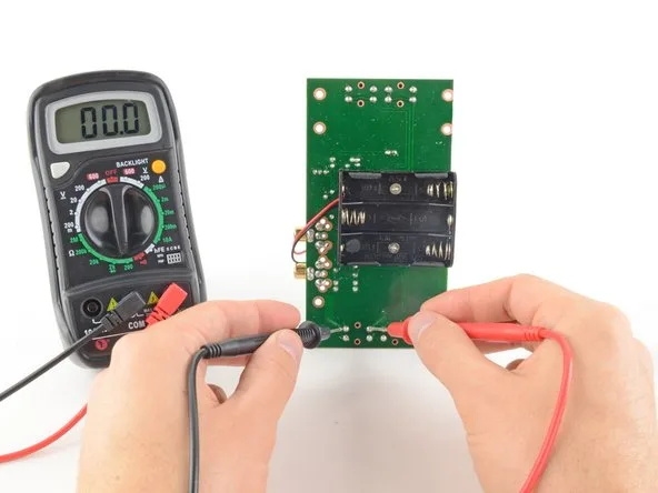
● Digital Multimeter: An indispensable tool for measuring voltage, current, and resistance. Prioritize models featuring a continuity test function to efficiently detect breaks in circuit traces. A reliable model can typically be acquired for $10–$30.
● Adjustable DC Power Supply: A variable power supply (e.g., 5V–12V, 1–2A) is required to power your PCB during testing. These adjustable units can be found online for as little as $20.
● Test Probes: Opt for fine-tip probes or alligator clips to ensure precise connections to small PCB pads and component leads. A set generally costs under $5.
● Pogo Pins: These spring-loaded pins are ideal for establishing consistent and reliable contact with designated test points on your PCB without soldering. A pack of 10 pogo pins typically ranges from $3–$5.
● Jig Base: A sturdy platform, such as a breadboard or a custom-fabricated base, is needed to securely mount your PCB and connect test points. A small breadboard is quite affordable, around $5.
● Microcontroller (Optional for Automation): For those interested in building an Arduino PCB tester, a microcontroller like an Arduino Uno ($20–$25) can automate various testing procedures.
● Miscellaneous Supplies: Essential hand tools include a soldering iron, solder, various wires, and a magnifying glass for detailed visual inspection of minuscule components.
With an estimated budget of less than $100, you can assemble a fully functional homemade PCB tester capable of addressing fundamental diagnostic requirements.
Step-by-Step Guide to Constructing a PCB Test Jig
Once your tools are assembled, the next step involves building a PCB test jig. This custom fixture is designed to firmly hold your PCB in place and facilitate effortless connections to specific test points. Follow these instructions to create an effective, yet simple, test jig.
Building the Jig
● Step 1: Design Your Test Jig Layout: Begin by thoroughly analyzing the PCB you intend to test. Identify all critical test points, including power rails, ground pads, and essential signal lines. Create a detailed sketch or digital layout for your jig, precisely mapping the positions where pogo pins or probes will align with these test points. For testing multiple identical boards, absolute precision in this phase is paramount to ensure consistent and repeatable results.
● Step 2: Select a Jig Base Material: Choose a robust material for your jig's base, such as acrylic, wood, or even a repurposed breadboard. Drill precise holes or install dedicated holders for the pogo pins at the exact coordinates corresponding to your PCB’s test points. For a more refined and professional fixture, consider utilizing 3D printing if you have access to the technology, which allows for highly customized bases.
● Step 3: Install Pogo Pins or Probes: Securely insert the pogo pins into the pre-drilled holes in your base. These spring-loaded components will make electrical contact with the PCB without requiring any soldering. Wire the opposite end of each pogo pin to a terminal strip or directly to your multimeter probes. Ensure impeccable alignment of the pins to prevent any potential damage to the PCB under test.
● Step 4: Implement a Clamping Mechanism: To maintain the PCB's stability throughout the testing process, integrate a straightforward clamping mechanism. This could be as simple as using elastic bands or small screws to firmly press the board against the pogo pins. Maintaining stability is key to ensuring consistent electrical contact during diagnostics.
● Step 5: Validate the Jig Setup: Position your PCB onto the assembled jig. Apply power to the board and use your multimeter to verify voltages at critical points. For instance, if your board is designed for 5V operation, confirm that the power rail reads approximately 5V (within a typical tolerance of ±0.1V). Additionally, perform continuity checks on vital traces to confirm there are no breaks or open circuits.
Establishing an Optimized PCB Test Environment
Beyond the physical construction of a test jig, setting up an efficient PCB test environment is equally important for minimizing errors and maximizing diagnostic accuracy. Here are some recommendations to enhance your testing area.
Optimizing Your Workspace
● Organized and Static-Free Workspace: Maintain a meticulously organized workspace. Utilize a static-free mat to protect your types of PCBs from electrostatic discharge (ESD) damage, which can be purchased for as little as $10.
● Adequate Illumination: Employ a bright desk lamp or a magnifying lamp to facilitate close inspection of small components and intricate solder joints. Magnifying lamps are generally available for $15–$30.
● Thorough Documentation: Keep a detailed notebook or digital log to record all test results, such as resistance values (e.g., identifying a 1.2 kΩ reading where 1 kΩ is expected) or observed voltage drops. This documentation is invaluable for future reference and troubleshooting.
● Strict Safety Protocols: Always disconnect power from the PCB before making any connections or adjustments to prevent electrical shocks or accidental short circuits.
A thoughtfully designed PCB test environment not only ensures accurate diagnostics but also safeguards both the operator and the circuit boards during testing procedures.
Building an Arduino PCB Tester for Automated Diagnostics
For hobbyists or engineers seeking to advance their DIY PCB testing capabilities, an Arduino PCB tester offers a robust solution for automating repetitive tasks and providing precise digital readouts of test results. By integrating a microcontroller like Arduino, you can measure voltages, conduct continuity tests, and even log data for later analysis.
Getting Started with Arduino Automation
● Step 1: Gather Arduino Components: You will need an Arduino board (e.g., Uno or Nano, typically $20–$25 ), a small LCD display ($5–$10) for displaying results, a selection of resistors for voltage dividers, and jumper wires for connections. For audible alerts, an optional buzzer can be included.
● Step 2: Develop Basic Testing Code: Program the Arduino to read analog voltages from specific pins connected to the PCB’s test points. For example, use the analogRead() function to monitor a signal line expected to be 3.3V. If the measured voltage deviates outside a predefined tolerance (e.g., ±0.2V), the Arduino can activate a warning message on the LCD or trigger the buzzer.
● Step 3: Integrate with Your Test Jig: Connect the Arduino's digital and analog pins to the pogo pins or probes within your PCB test jig. This integration allows the microcontroller to concurrently monitor multiple test points, significantly reducing manual testing time.
● Step 4: Test and Refine the Setup: Upload your code to the Arduino, power the HDI PCB under test, and observe the results displayed on the LCD. Continuously refine your code to incorporate advanced features, such as data logging via a serial connection to a computer for in-depth analysis and record-keeping.
Leveraging Open Source Solutions for PCB Testing
For individuals who may not have extensive coding experience, a wealth of open source PCB testing resources can be leveraged. Numerous online communities and platforms provide free access to schematics, source code, and comprehensive guides for constructing various types of PCB testers. For instance, many Arduino-based testing projects are openly available on popular open-source hardware forums. These resources often come with detailed instructions and benefit from community support, making it easier to develop a reliable homemade PCB tester.
Some open-source projects focus specifically on component testing (e.g., identifying resistor values or assessing capacitor health), while others are designed for full PCB diagnostics. Often, downloadable firmware can be readily customized to meet specific testing requirements, saving significant development time.
Common PCB Issues Detectable with Your DIY Setup
With your DIY PCB testing setup fully operational, it’s time to apply it to real-world diagnostics. Here are some of the most common PCB issues you can effectively identify using your affordable diagnostic tools:
Diagnosing Typical PCB Faults
● Short Circuits: Utilize the continuity mode of your multimeter to check for unintended electrical connections between traces or pads. A reading close to 0Ω is a strong indicator of a short circuit.
● Open Circuits: Test individual traces and solder joints for breaks or discontinuities. The absence of continuity (indicated by infinite resistance) suggests an open circuit.
● Voltage Irregularities: Measure voltages on power rails to ensure they align with expected values (e.g., 5V ±0.1V). Significant deviations can point to a faulty voltage regulator, an improperly loaded power rail, or a failing capacitor.
● Component Failures: Test individual components like resistors (e.g., an expected 10 kΩ resistor reading 12 kΩ) or diodes to confirm they are functioning within their specified parameters.
By systematically inspecting these areas, you can precisely pinpoint and resolve issues before they escalate into larger problems within your electronic projects.
Ensuring Accuracy and Expanding Your Testing Capabilities
To guarantee that your homemade PCB tester consistently provides reliable and accurate results, adhere to these maintenance and calibration guidelines. As your expertise grows, consider expanding your setup to handle more intricate boards or to automate larger testing batches.
Maintaining Accuracy and Scaling Up
● Multimeter Calibration: Periodically verify the accuracy of your multimeter against a known reference voltage or resistance standard.
● Clean Test Points: Keep pogo pins and test probes meticulously clean and free from dirt or oxidation to ensure consistent and reliable electrical contact with the PCB.
● Secure Connections: Always double-check all wiring and connections. Loose wires or poor contacts can lead to erroneous readings and diagnostic misinterpretations.
● Arduino Code Updates: If you are utilizing an Arduino PCB tester, regularly update your code to incorporate new test scenarios, enhance accuracy, or fix bugs.
Scaling Up Your Diagnostic Station
● Automated Test Sequences: Program your Arduino to execute a complete diagnostic sequence on each board, automatically logging pass/fail results for batch testing.
● Advanced Instrumentation: Consider investing in more advanced yet affordable tools, such as a low-cost oscilloscope (starting around $50), to analyze signal integrity, for example, checking for noise on a 1 MHz clock signal.
● Custom Software Interface: Develop a simple PC-based interface to visualize and manage test data streamed from your Arduino over a serial connection.
These enhancements can transform your basic setup into a semi-professional diagnostic station without incurring the high costs associated with commercial equipment.
Begin Your DIY PCB Testing Journey Today!
Constructing a DIY PCB diagnostic station is a fulfilling project that equips you with the essential tools to effectively test and troubleshoot circuit boards. From engineering a straightforward PCB test jig with pogo pins to automating complex diagnostics using an Arduino PCB tester, the possibilities for customization and capability are vast. By judiciously using affordable diagnostic tools and leveraging the rich ecosystem of open-source PCB testing resources, you can create a reliable homemade PCB tester perfectly tailored to your individual requirements.
Start modestly with fundamental tools such as a multimeter and probes, establish an organized and functional PCB test environment, and progressively enhance your setup as your projects increase in complexity. With the detailed steps and practical advice provided in this guide, you are well-prepared to master PCB diagnostics efficiently and economically. Begin building your testing setup today and ensure your circuit boards are always ready for peak performance!


