Introduction
In the realm of audio electronics, achieving clear sound reproduction while managing costs presents a persistent challenge for electric engineers. CEM-1 emerges as a compelling material choice for PCB audio amplifier designs, particularly in single-layer configurations where simplicity drives both performance and affordability. This composite epoxy material balances essential electrical and thermal properties with economic advantages, making it suitable for low to mid-power audio applications. Engineers often overlook CEM-1 in favor of more robust laminates, yet its attributes align well with the demands of straightforward amplifier circuits. By leveraging CEM-1, designers can deliver cost-effective audio electronics without compromising fundamental sound clarity. This article explores the technical rationale behind using CEM-1 PCB audio amplifiers, from material fundamentals to design best practices.
What Is CEM-1 and Why It Matters for Audio Amplifiers
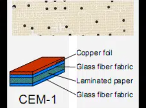
CEM-1, or Composite Epoxy Material grade 1, consists of a cellulose paper core sandwiched between thin glass fabric layers impregnated with epoxy resin. This construction provides a flame-retardant, mechanically stable base ideal for single-layer audio PCBs. Unlike glass-reinforced epoxies, CEM-1 prioritizes cost reduction through its paper-based core, which lowers raw material expenses while maintaining punchability and dimensional stability during fabrication. For audio amplifier PCB design, this matters because amplifiers generate heat from power transistors and require materials that resist warping under thermal stress.
The relevance of CEM-1 in audio applications stems from its suitability for low-frequency circuits, where signal integrity remains intact without multilayer complexity. Cost-effective audio electronics benefit from CEM-1's ability to support through-hole components common in amplifier builds, reducing assembly costs. Engineers value its compliance with established laminate specifications, ensuring reliability in consumer-grade products. In essence, CEM-1 enables engineers to prototype and produce amplifiers that deliver clear sound at a fraction of the cost of premium materials.
Technical Principles of CEM-1 in Audio Amplifier Design
The core mechanism enabling CEM-1's performance in audio amplifiers lies in its hybrid laminate structure, which offers balanced dielectric properties for signal propagation. The glass-epoxy surfaces provide smooth copper adhesion, minimizing surface defects that could introduce noise in audio paths. Cellulose core contributes to low moisture absorption in controlled environments, preserving electrical insulation during operation. Thermal dissipation in CEM-1 PCB audio amplifiers relies on its inherent conductivity pathways and compatibility with heatsinks, crucial for managing junction temperatures in output stages.
Signal fidelity in single-layer audio PCB designs using CEM-1 depends on careful trace routing to avoid ground loops, a common issue in amplifiers. The material's stability under soldering temperatures supports reliable joint formation, adhering to qualification standards like IPC-6012 for rigid boards. CEM-1 thermal performance in audio contexts shines in applications with moderate power dissipation, where convection cooling suffices without exotic substrates. Engineers must account for the material's CTE, ensuring component leads align post-fabrication to prevent microcracks.
Vibration resistance further underscores CEM-1's fit for audio housings, as the composite dampens mechanical resonances that could modulate sound waves. Electrical breakdown strength supports high-voltage rails in class AB amplifiers, maintaining clear output without arcing. Overall, these principles position CEM-1 as a pragmatic choice for engineers prioritizing audio amplifier PCB design efficiency.
CEM-1 Thermal Performance in Audio Applications
Effective thermal management defines the longevity of audio amplifiers, and CEM-1 delivers adequate performance for non-extreme designs. Heat from Darlingtons or MOSFETs spreads via copper planes, with the laminate acting as a thermal barrier to chassis mounting. Unlike higher-end materials, CEM-1 avoids excessive rigidity that could impede flexible thermal vias in single-layer setups. Its epoxy formulation resists delamination during repeated power cycles, a key factor in audio testing protocols.
CEM-1 thermal performance audio benefits extend to reflow processes, where the material withstands peak temperatures without charring the core. Engineers design ground planes to double as heat spreaders, enhancing dissipation in compact enclosures. Compliance with acceptability criteria in IPC-A-600 ensures boards pass visual and electrical inspections post-thermal stress. For cost-effective audio electronics, this translates to fewer rejects and faster time-to-market.
Considerations include pad sizing for transistors, oversized to maximize contact with heatsinks. Ambient conditions influence performance, prompting conservative derating in humid climates. Ultimately, CEM-1 proves thermal performance audio reliability through practical engineering rather than over-specification.
Best Practices for Audio Amplifier PCB Design with CEM-1
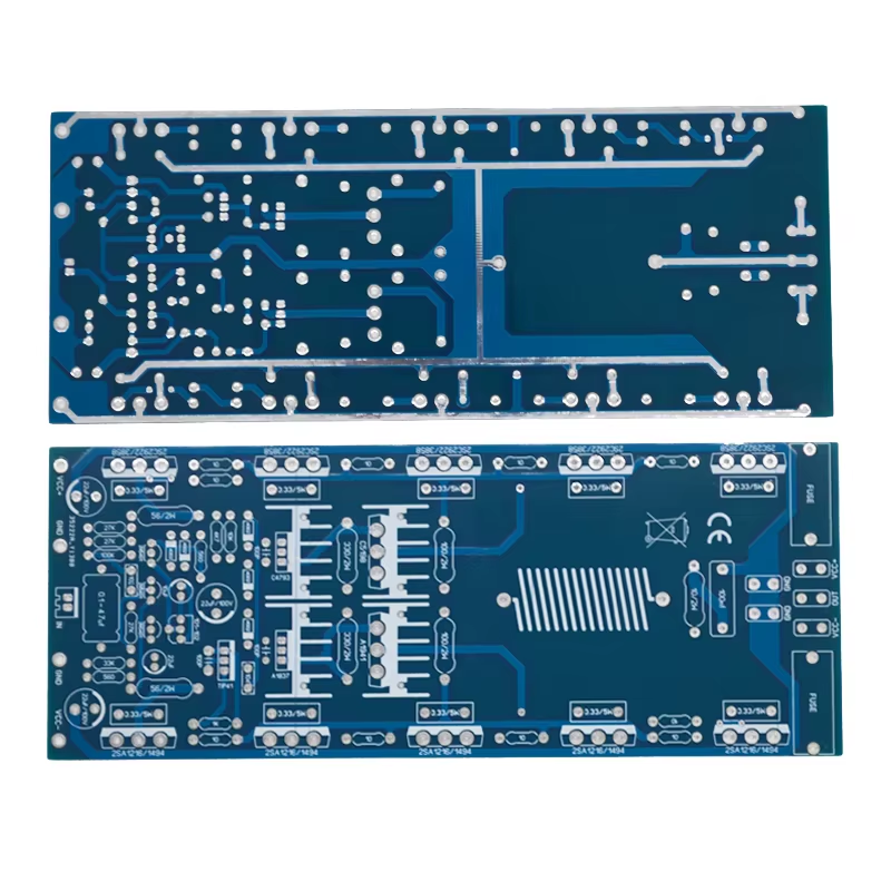
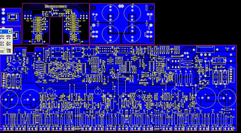
Start with schematic validation emphasizing star grounding to suppress hum in CEM-1 PCB audio amplifier layouts. Single-layer constraints demand strategic component placement: position feedback loops close to op-amps to shorten traces and reduce pickup. Use 2 oz copper for power paths, enhancing current handling without multilayer etching. Adhere to IPC-4101 specifications for base materials to guarantee laminate uniformity across panels.
Routing prioritizes analog sections away from power entry points, preserving signal-to-noise ratios vital for clear sound. Incorporate decoupling capacitors near IC supplies, leveraging CEM-1's stable dielectric for low ESR. Solder mask application protects traces from oxidation, extending shelf life in audio electronics. Test fixtures simulate load conditions early, verifying thermal profiles before production.
For assembly, through-hole dominates in single-layer audio PCB, suiting wave soldering for high yields. Stencil design accommodates tall components like electrolytics, preventing bridging. Post-assembly bake-out removes fluxes, aligning with J-STD cleanliness standards. These practices yield robust, cost-effective designs ready for volume runs.
Troubleshooting Common Issues in CEM-1 Audio PCBs
Noise injection often plagues initial prototypes; isolate digital controls if present, using ferrite beads on CEM-1 boards. Thermal runaway manifests as distortion, addressed by adding thermal cutoffs or NTC sensors. Warpage from uneven cooling during fabrication responds to controlled fixturing per IPC guidelines. Measure impedance mismatches with network analyzers to tune input networks.
Component drift under heat requires selecting parts with matching coefficients to CEM-1's properties. Hum from ground currents demands lift points or virtual grounds. Electrolytic failures stem from ripple currents; parallel ceramics mitigate this in power supplies. Systematic logging during burn-in reveals patterns, guiding iterative refinements.
Firmware glitches in hybrid amps exacerbate issues; verify timing with scopes. Mechanical stress from mounting torques causes trace lifts; use washers. These troubleshooting steps ensure CEM-1 audio amplifiers perform consistently.
Conclusion
CEM-1 stands out as a cost-effective cornerstone for single-layer audio PCB designs, delivering clear sound through reliable thermal and electrical properties. Electric engineers appreciate its fabrication ease and alignment with industry standards, enabling scalable production. From low-frequency amps to portable systems, CEM-1 thermal performance audio supports practical innovation without excess cost. Prioritizing best practices in layout and assembly unlocks its full potential. As demands for affordable high-fidelity electronics grow, CEM-1 remains a strategic material choice.
FAQs
Q1: What makes CEM-1 suitable for CEM-1 PCB audio amplifier designs?
A1: CEM-1's composite structure provides dimensional stability and flame retardancy essential for single-layer boards in amplifiers. It supports through-hole assembly common in audio circuits, reducing costs while maintaining signal integrity. Thermal properties handle moderate dissipation from output stages, ensuring clear sound reproduction without multilayer expense. Compliance with laminate specs further validates its use in production.
Q2: How does CEM-1 compare to other materials in audio amplifier PCB design?
A2: In audio amplifier PCB design, CEM-1 excels in cost-effective audio electronics for simple topologies, offering better punchability than glass epoxies. It lags in high-frequency response but suffices for audio bands. Single-layer audio PCB applications benefit from its low warpage during soldering. Engineers select it for prototypes where budget trumps extreme thermal demands.
Q3: What are key considerations for CEM-1 thermal performance audio?
A3: CEM-1 thermal performance audio hinges on copper plane sizing and heatsink integration to dissipate power transistor heat. Avoid overcrowding to permit airflow in enclosures. Design per qualification standards prevents delamination under cycles. For cost-effective setups, monitor junction temperatures conservatively to extend reliability.
Q4: Can single-layer audio PCB using CEM-1 achieve clear sound?
A4: Yes, single-layer audio PCB with CEM-1 delivers clear sound by minimizing parasitics through optimized routing. Ground plane strategies suppress noise, vital for fidelity. Practical assembly yields match multilayer for low-power amps. Target low-distortion layouts to leverage the material's stability.
References
IPC-4101B — Specification for Base Materials for Rigid and Multilayer Printed Boards. IPC.
IPC-6012E — Qualification and Performance Specification for Rigid Printed Boards. IPC, 2017.
IPC-A-600K — Acceptability of Printed Boards. IPC, 2020.


