What is a PCB Fuse and Why is it Essential?
In the rapidly evolving electronics industry, safeguarding printed circuit boards (PCBs) from overcurrent events is paramount for ensuring device reliability and overall safety. PCB fuses serve as a fundamental line of defense, protecting sensitive components from potential damage caused by short circuits, overloads, or sudden voltage spikes. The correct selection of a fuse for your PCB design can be the deciding factor between a robust, durable product and one prone to costly failures. This guide will explore the essential aspects of PCB fuses, including their various types, crucial selection criteria, and recommended best practices to assist engineers in making informed design decisions.
The Role of Fuses in Circuit Protection
A PCB fuse is a compact, sacrificial device directly integrated onto a circuit board, designed specifically to protect circuits from excessive electrical current. When the current flowing through a circuit surpasses the fuse's specified rating, its internal element—typically a fine metal wire or strip—rapidly melts. This action effectively breaks the circuit, thereby preventing current overload and averting potential damage to downstream components. This swift interruption minimizes severe risks such as overheating, permanent component failure, or even fire hazards. For instance, within a smartphone PCB, a strategically placed fuse can shield delicate integrated circuits (ICs) from a short circuit originating from a faulty battery, preserving the device's functionality and lifespan.
Without adequate overcurrent protection, excessive current can cause extensive damage. This can range from melting solder joints and burning PCB traces to causing irreversible harm to integrated circuits. Industry analyses suggest that overcurrent events contribute to approximately 30% of electronic device failures, underscoring the critical importance of fuses in PCB design. By acting as a precisely engineered weak link, fuses ensure that electrical faults are isolated effectively before they can cascade through and compromise the entire system.
What Are the Different Types of PCB Fuses?
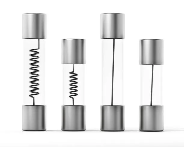
PCB fuses are available in various configurations, each engineered for specific applications and performance requirements. A comprehensive understanding of these options is crucial for selecting the most appropriate fuse for any given design.
Common Fuse Types and Their Applications
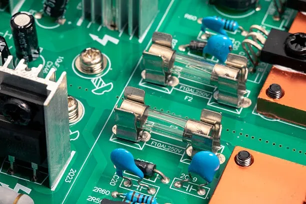
● Surface-Mount Device (SMD) Fuses: These are miniature devices designed to be soldered directly onto the PCB's surface. Their compact size makes them ideal for high-density modern electronics like smartphones and laptops. Available in standard package sizes (e.g., 1206, 0805), SMD fuses offer current ratings typically from 0.5A to 10A and voltage ratings up to 250V. Their small footprint and compatibility with automated assembly processes make them a popular choice for designs where space is at a premium.
● Through-Hole Fuses: Equipped with wire leads that are inserted into drilled holes on the PCB, through-hole fuses are utilized in applications demanding greater mechanical strength, such as robust industrial control systems. These fuses are generally easier to replace manually and can accommodate higher current ratings, often exceeding 20A. However, their larger physical size makes them less suitable for compact electronic designs.
● Resettable (PTC) Fuses: Polymeric Positive Temperature Coefficient (PPTC) fuses, commonly known as resettable fuses, possess the unique characteristic of not requiring replacement after a trip event. When an overcurrent occurs, the polymer material inside the fuse rapidly heats up, causing its resistance to increase significantly and thereby limiting current flow. Once the fault condition is cleared and the fuse cools down, it automatically resets. These fuses are an excellent choice for applications prone to frequent transient surges, such as USB ports or telecommunications equipment, with typical trip currents ranging from 0.1A to 5A.
● Fast-Blow vs. Slow-Blow Fuses: Fuses are also categorized by their response speed to overcurrent conditions. Fast-blow fuses react almost instantaneously, making them ideal for protecting highly sensitive components like microcontrollers, where even a momentary surge could cause irreparable damage. In contrast, slow-blow fuses are designed to tolerate brief, temporary current surges—such as the inrush currents that occur during capacitor charging or motor startup. They are commonly employed in power supplies or motor drive circuits. For example, a 2A slow-blow fuse might safely withstand a 4A surge for 100 milliseconds without blowing.
What Are the Key Factors in PCB Fuse Selection?
Selecting the appropriate PCB fuse necessitates a thorough evaluation of several electrical and environmental parameters. A systematic approach ensures optimal protection and performance.
Critical Parameters for Fuse Selection
● Current Rating: This specifies the maximum continuous current a fuse can carry without tripping. To select the correct rating, calculate the circuit's normal operating current and then incorporate a safety margin, typically 20-25%. For instance, if a circuit normally draws 1.6A, a 2A fuse provides sufficient protection while minimizing nuisance tripping. Under-sizing the fuse leads to frequent blowouts, whereas over-sizing risks inadequate protection during actual fault conditions.
● Voltage Rating: The voltage rating defines the maximum voltage the fuse can safely interrupt. This rating must be equal to or greater than the circuit's operating voltage. For example, a 12V automotive PCB should use a fuse rated for at least 12V, though higher voltage ratings like 32V or 125V are often used for enhanced safety margins. Using a fuse with an insufficient voltage rating can lead to dangerous arcing or a failure to effectively break the circuit during an overcurrent event.
● Breaking Capacity (Interrupting Rating): This critical parameter indicates the maximum fault current a fuse can safely interrupt without sustaining damage to itself or its surroundings. In high-power systems, short-circuit currents can potentially reach thousands of amperes. A typical SMD fuse might have a breaking capacity of 50A at 32V, while heavy-duty industrial fuses can handle up to 10,000A. It is paramount to ensure that the fuse's breaking capacity always exceeds the calculated worst-case fault current for your specific circuit.
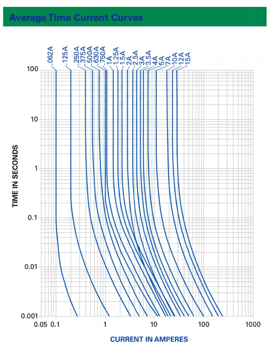
● Response Time (Time-Current Curve): The fuse's time-current characteristic curve illustrates how quickly it responds to different levels of overcurrent. Fast-blow fuses are ideal for highly sensitive electronics, reacting within milliseconds, whereas slow-blow fuses are designed to accommodate brief, transient surges, making them suitable for circuits experiencing high inrush currents. Careful review of the circuit's requirements and the tolerance levels of its components is essential for choosing the appropriate response time.
● Environmental Considerations: Operating conditions, including ambient temperature, humidity, and vibration, can significantly impact a fuse's performance and lifespan. For example, fuses used in demanding automotive or marine applications may need to withstand extreme temperatures ranging from -40°C to 125°C or be resistant to moisture ingress. Specialized sealed fuses or those constructed with low-inductance materials are designed for such harsh environments. Always consult the fuse's datasheet for its specified environmental ratings to ensure it meets the application's demands.
Best Practices for Integrating Fuses into PCB Designs
Proper fuse integration is vital for enhancing circuit reliability and simplifying maintenance. Adhering to certain best practices can significantly optimize your PCB design.
Design and Placement Guidelines
● Proximity to Power Source: Always position the fuse as close as possible to the main power input—whether it's a battery, power supply, or external connector. This strategic placement ensures that the entire downstream circuit is protected from an overcurrent event at its earliest point, minimizing the risk of widespread damage.
● Accessibility Considerations: For through-hole or user-replaceable fuses, design the layout such that they are easily accessible for inspection, testing, and replacement. In compact designs, SMD fuses are typically wave-soldered during automated assembly for manufacturing efficiency.
● Pre-Deployment Testing: Incorporate continuity and comprehensive electrical tests during the SMD PCB assembly phase to thoroughly verify the fuse's functionality. This ensures that the fuse operates precisely within its specified parameters before the device is deployed.
● Expert Consultation: For complex or high-stakes applications, engage with experienced engineers or manufacturers to validate your fuse selection. Their specialized insights can help prevent costly design oversights and ensure robust protection.
● Adherence to Industry Standards: Confirm that all selected fuses comply with recognized industry standards, such as UL (Underwriters Laboratories) or IEC (International Electrotechnical Commission) certifications, to guarantee safety and consistent reliability.
Common Mistakes to Avoid
Even seasoned engineers can make errors when selecting or integrating PCB fuses. Being aware of these common pitfalls can prevent significant issues.
● Ignoring Inrush Currents: A frequent mistake is failing to account for temporary inrush currents, which can lead to frustrating nuisance tripping. Using slow-blow fuses or carefully consulting component datasheets to estimate peak currents can mitigate this.
● Insufficient Breaking Capacity: Employing a fuse with an inadequate breaking capacity can be catastrophic, as it may fail to interrupt extremely high fault currents, potentially causing extensive damage or creating serious safety hazards.
● Neglecting Derating: High ambient temperatures significantly reduce a fuse's current-carrying capacity. Always apply appropriate derating factors (e.g., a 0.8x derating for environments operating at 85°C) to ensure reliable and consistent operation under thermal stress.
● Using Non-Certified Fuses: Opting for uncertified or low-quality fuses can result in inconsistent performance and compromise overall safety. Always source fuses from reputable, trusted manufacturers who provide proper certifications.
AIVON's Support for PCB Fuse Integration
At AIVON, a well-known online PCB manufacturer, we deeply understand the critical importance of reliable overcurrent protection in PCB design. Our advanced manufacturing capabilities and rapid-turn prototyping services are designed to empower engineers to meticulously test and refine fuse integration with utmost precision. Leveraging efficient global logistics and a steadfast commitment to high-quality standards, we deliver PCBs that perfectly match your exact specifications, whether your design is for sophisticated consumer electronics or robust industrial applications. Furthermore, our team of expert engineers is readily available to offer specialized guidance on component selection, ensuring that your chosen fuses align perfectly with your circuit's specific protection requirements.
Conclusion: Mastering Fuse Selection for Reliable PCB Design
Choosing the correct PCB fuse is a pivotal step in designing reliable, safe, and highly efficient electronic systems. By thoroughly understanding the different types of fuses, carefully considering key selection criteria, and implementing best practices for their integration, engineers can effectively protect their circuits from damaging overcurrent events and significantly extend the longevity of their devices. Whether your design calls for a compact SMD fuse or a resettable PTC fuse for transient protection, meticulous planning and rigorous testing are indispensable. At AIVON, we are dedicated to supporting your journey with high-quality PCBs and expert guidance every step of the way. Take the necessary time to thoroughly evaluate your circuit's unique needs, consult with professionals, and select a fuse that guarantees robust overcurrent protection for your next project.


