Introduction
Designing a high power thick PCB presents unique challenges for electrical engineers, especially when handling high current and significant thermal loads. Component selection plays a critical role in ensuring reliability, efficiency, and safety in such applications. These boards often power industrial systems, automotive electronics, and renewable energy setups, where failure is not an option. This article explores the key considerations for selecting components on a high power PCB, focusing on compatibility with high current demands and effective thermal management using heat sinks. Written for design engineers, this guide provides practical insights into building robust systems while adhering to industry standards. The goal is to equip professionals with the knowledge to optimize their designs for performance and longevity.
What Is a High Power Thick PCB and Why It Matters
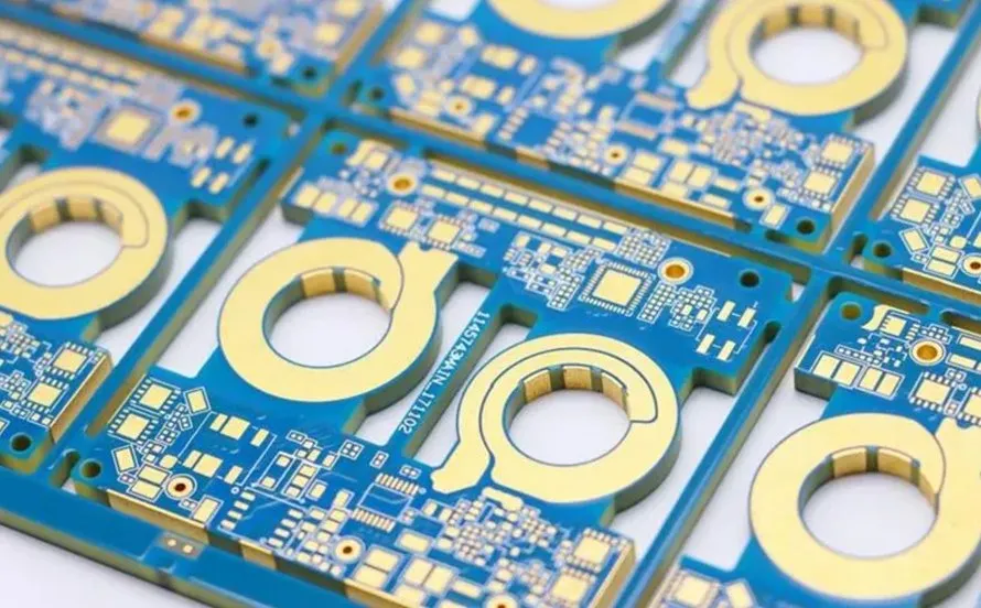
A high power thick PCB is a specialized printed circuit board designed to handle substantial electrical power, often involving currents exceeding tens of amperes and voltages in the hundreds. Unlike standard boards, these feature thicker copper layers, typically ranging from 3 oz/ft2 to 10 oz/ft2 or more, to accommodate high current without excessive resistive losses. They are essential in applications like electric vehicle chargers, industrial motor drives, and power inverters, where energy efficiency and thermal stability are paramount.
The importance of such boards lies in their ability to prevent overheating, voltage drops, and component degradation under demanding conditions. Poor design or component selection can lead to catastrophic failures, including short circuits or thermal runaway. For design engineers, understanding the interplay between PCB layout, component ratings, and heat dissipation is vital to meeting performance and safety requirements in high power systems.
Technical Principles of Component Selection for High Power PCBs
Selecting components for a high power thick PCB involves understanding several technical principles. First, current carrying capacity is a primary concern. Components must be rated to handle the maximum expected current without overheating or degrading. This requires evaluating the current ratings of connectors, capacitors, inductors, and power semiconductors like MOSFETs or IGBTs. Standards such as IPC-2221B provide guidelines for determining trace widths and copper thickness to support high current paths on the fast turn PCB.
Second, voltage ratings are equally critical. Components must withstand the system's operating voltage, including transients and spikes. Overlooking this can result in dielectric breakdown or arcing, especially in high power environments. Design engineers must also consider derating guidelines to ensure components operate below their maximum limits for enhanced reliability.
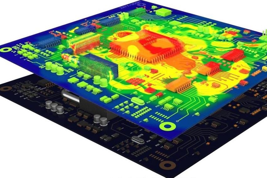
Third, thermal performance directly impacts component longevity. High current generates heat through resistive losses, necessitating components with low thermal resistance and high temperature tolerances. Heat sinks are often integrated to dissipate this heat, and their effectiveness depends on proper component placement and thermal interface materials. Adhering to standards like IPC-7351B for land pattern design helps ensure optimal heat transfer.
Finally, electromagnetic interference must be addressed. High current switching in power electronics can induce noise, affecting nearby components. Selecting parts with appropriate shielding or filtering characteristics is essential to maintain signal integrity and comply with electromagnetic compatibility requirements outlined in standards like IEC 61000 series.
Practical Solutions for Component Selection on High Power PCBs
Assessing Component Specifications
Design engineers must start by thoroughly reviewing datasheets for current, voltage, and thermal ratings. Ensure that selected components meet or exceed the system's maximum operating conditions. For instance, power resistors and capacitors should have ratings well above expected values to account for transients. Applying a derating factor, often 20 to 30 percent below maximum ratings, enhances reliability under continuous high power operation.
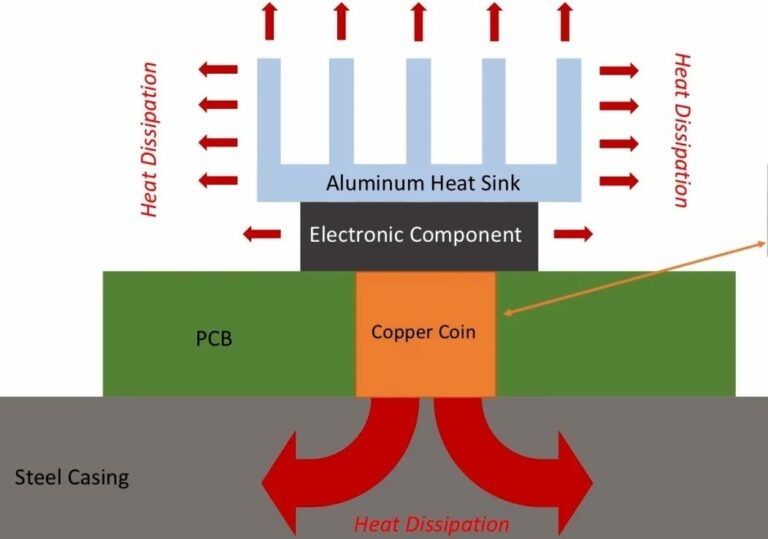
Prioritizing Thermal Management with Heat Sinks
Heat sinks are indispensable for managing thermal loads in high power PCBs. Choose components with exposed thermal pads or metal cases that facilitate direct mounting to heat sinks. Ensure the heat sink's thermal resistance and surface area are sufficient to keep junction temperatures within safe limits. Proper mounting techniques and thermal interface materials are crucial for efficient heat transfer. Following guidelines from standards like IPC-7095D for component placement aids in optimizing thermal dissipation.
Suggested Reading: Managing Heat in High Power Multilayer PCB Designs
Selecting Components for High Current Paths
For high current applications, prioritize components with low equivalent series resistance and high current handling capacity. Connectors, for example, must have robust contact designs to minimize voltage drops. Similarly, power semiconductors should feature low on resistance to reduce heat generation. Trace layouts should comply with IPC-2221B to prevent current bottlenecks and ensure even distribution across the PCB.
Mitigating Electromagnetic Interference
High current switching often generates electromagnetic interference, affecting component performance. Opt for components with built in filtering or shielding capabilities. Place decoupling capacitors close to power pins of active components to suppress noise. Layout considerations, as outlined in IPC-7351B, help minimize loop areas and reduce interference in high power designs.
Troubleshooting Common Issues in High Power PCB Designs
In my experience as an assembly engineer, several recurring issues arise during component selection for high power thick PCBs. One common problem is thermal mismatch between components and heat sinks, leading to inefficient cooling. This often stems from inadequate thermal interface material or poor mounting pressure. Always verify the contact surface and use materials compliant with industry standards to ensure optimal heat transfer.
Another frequent challenge is component failure due to insufficient current ratings. I have seen designs fail because connectors or passives were not specified for peak currents during transients. Cross checking specifications against system requirements and applying derating practices can prevent such issues.
Lastly, electromagnetic interference can disrupt operation if not addressed early. I recommend testing prototypes under full load conditions to identify noise sources. Adjusting component placement or adding filtering elements often resolves these problems. Standards like IEC 61000 provide valuable guidance for achieving compliance in high power environments.
Conclusion
Component selection for a high power thick PCB demands careful consideration of current ratings, voltage tolerances, and thermal management strategies. Design engineers must prioritize components that can withstand the rigors of high current applications while integrating heat sinks to dissipate excess heat. By adhering to established industry standards and applying practical solutions, such as derating and noise mitigation, reliable and efficient designs are achievable. This process, though complex, ensures the longevity and safety of power electronics in demanding applications. With a structured approach, engineers can navigate the challenges of high power PCB design and deliver robust solutions.
FAQs
Q1: What factors should design engineers consider for high power PCB component selection?
A1: Design engineers must evaluate current and voltage ratings, thermal performance, and electromagnetic compatibility when selecting components for a high power PCB. Ensuring ratings exceed operating conditions, incorporating heat sinks for thermal management, and following standards like IPC-2221B for layout design are essential. Derating components further enhances reliability under continuous high current loads.
Q2: How do heat sinks improve high power PCB performance?
A2: Heat sinks dissipate excess heat generated by high current in a high power PCB, preventing component overheating and extending lifespan. They reduce junction temperatures by providing a larger surface area for heat transfer. Proper mounting and thermal interface materials, as per IPC-7095D guidelines, ensure efficient cooling and maintain system stability in demanding applications.
Q3: Why is high current a challenge in PCB design?
A3: High current in a PCB design creates challenges like resistive heat generation, voltage drops, and potential component failure. It requires thicker copper layers and components with robust ratings to prevent overheating. Standards such as IPC-2221B guide trace width calculations to handle current loads, ensuring safety and performance in high power systems.
Q4: How can electromagnetic interference be minimized on a high power PCB?
A4: Electromagnetic interference on a high power PCB can be minimized by selecting components with shielding or filtering capabilities and optimizing layout design. Place decoupling capacitors near power pins and reduce loop areas as per IPC-7351B guidelines. Testing under full load and adhering to IEC 61000 standards helps ensure compliance and signal integrity.
References
IPC-2221B — Generic Standard on Printed Board Design. IPC, 2012.
IPC-7351B — Generic Requirements for Surface Mount Design and Land Pattern Standard. IPC, 2010.
IPC-7095D — Design and Assembly Process Implementation for Ball Grid Arrays (BGAs). IPC, 2018.
IEC 61000 — Electromagnetic Compatibility (EMC) Series. IEC, various years.


