Introduction
For electronic hobbyists, crafting a printed circuit board (PCB) is both a creative and technical endeavor. One advanced technique that can elevate your DIY projects is controlled depth drilling. Often linked with back drilling, this method is crucial for maintaining signal integrity in high-speed designs. This guide aims to simplify controlled depth drilling for beginners, offering practical PCB drilling tips and insights into back drilling basics. Whether you are working on simple PCB projects or aiming to improve DIY PCB signal integrity, understanding this process can transform your results. Let's explore how hobbyists can approach controlled depth drilling with basic tools and knowledge, ensuring precision and performance in every board you create.
What Is Controlled Depth Drilling and Why It Matters
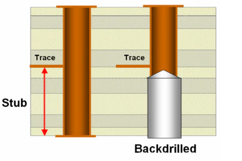
Controlled depth drilling refers to a specialized technique in PCB manufacturing where holes are drilled to a specific depth rather than passing through the entire board. Commonly known as back drilling in professional settings, it focuses on removing unused portions of plated through-hole (PTH) vias, often called stubs. These stubs can interfere with signal transmission in high-speed circuits by causing reflections and distortions.
For hobbyists, why does this matter? Even in simple PCB projects, poor signal quality can lead to unreliable performance. As you progress to more complex designs, maintaining DIY PCB signal integrity becomes essential. Controlled depth drilling helps minimize signal loss, especially when working with multilayer boards. While industrial applications use advanced machinery, hobbyists can adapt this concept using manual tools and careful planning. Recognizing its importance lays the foundation for cleaner, more efficient circuits in your projects.
Technical Principles of Controlled Depth Drilling
Controlled depth drilling operates on a straightforward principle: precision in hole depth to avoid unnecessary conductive material. In a typical PCB, vias connect different layers. When a via extends beyond the required connection point, the unused section acts as a stub. This stub can resonate at certain frequencies, disrupting high-speed signals.
The process involves drilling a hole slightly larger than the original via from the opposite side of the board to remove the stub. This ensures the via only connects the intended layers. For hobbyists, the challenge lies in achieving this precision without industrial equipment. Understanding the basics of back drilling involves knowing your board's layer stackup and identifying which vias need modification. Signal integrity issues often arise in designs above 1 GHz, but even lower-speed projects can benefit from cleaner connections.
Another key aspect is the aspect ratio of holes, which is the ratio of hole depth to diameter. Standards like IPC-6012E suggest maintaining specific ratios to ensure structural integrity during drilling. While hobbyists may not always follow strict guidelines, keeping holes proportional prevents board damage. Grasping these principles helps in planning your drilling approach effectively.
Practical PCB Drilling Tips for Beginners
Approaching controlled depth drilling as a hobbyist requires patience and the right techniques. Here are actionable steps to guide you through this process while working on simple PCB projects.
Start with Proper Planning
Before drilling, study your PCB design. Identify vias that connect only specific layers and mark those needing depth control. Use design software to visualize the layer stackup. Print a layout diagram to reference during the process. This step prevents errors and ensures you target the correct spots.
Choose the Right Tools
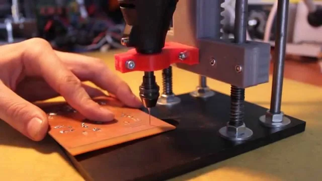
Hobbyists often lack access to CNC machines used in professional back drilling. Instead, use a precision hand drill or a small drill press. Select drill bits slightly larger than the via diameter to remove excess plating. A depth stop attachment on your drill can help control how deep you go. If unavailable, mark the bit with tape as a visual guide.
Test on Scrap Boards
Practice on a scrap PCB before working on your actual project. Drill test holes to gauge depth control. Measure the depth with a caliper to verify accuracy. This builds confidence and helps refine your technique without risking your main board.
Work Slowly and Measure Often
Drill in small increments, checking depth frequently. Avoid rushing, as over-drilling can damage inner layers. Use a magnifying glass to inspect the hole and ensure you have not penetrated too far. Patience is key to maintaining DIY PCB signal integrity.
Clean and Inspect
After drilling, remove debris with compressed air or a soft brush. Inspect the board for unintended damage. If the hole appears uneven, consider using a small file to smooth edges. This prevents short circuits or weak connections.
These PCB drilling tips for beginners focus on manual methods suitable for hobbyists. While not as precise as industrial processes, they can still improve performance in your designs.
Adapting Back Drilling Basics for DIY Projects
Back drilling basics revolve around the concept of stub removal, as mentioned earlier. For hobbyists, adapting this to DIY settings involves simplifying the approach. Start with single-sided or double-sided boards before tackling multilayer designs. These simpler boards reduce the risk of damaging critical inner layers.
Focus on projects where signal integrity matters, such as radio frequency circuits or microcontroller boards with fast clock speeds. Identify critical vias by reviewing your schematic for high-speed signal paths. Not all vias need back drilling, so prioritize those affecting performance.
Without advanced equipment, rely on manual depth control. Use a steady hand and consistent pressure while drilling. If possible, secure the fast turn PCB in a vise to prevent movement. Consider using a drill press for better stability over handheld tools. These adaptations make controlled depth drilling accessible for simple PCB projects.
One challenge hobbyists face is ensuring the drilled hole aligns perfectly with the original via. Misalignment can sever connections or create shorts. To avoid this, use a center punch to mark the exact spot before drilling. This small step enhances precision in your DIY efforts.
Troubleshooting Common Issues in Hobbyist Drilling
Even with careful planning, issues can arise during controlled depth drilling. Here are common problems and solutions tailored for hobbyists.
Over-Drilling
Drilling too deep can cut through necessary connections. Prevent this by setting a clear depth limit on your tool. If it happens, assess the damage. Minor errors might be fixable with conductive epoxy to reconnect layers, though this is not ideal for high-speed signals.
Misaligned Holes
If the drilled hole misses the via, it can create an open circuit. Avoid this by double-checking alignment before starting. Use a fine-tip marker to outline the via location. If misalignment occurs, you may need to redesign the board or use jumper wires as a workaround.
Debris Buildup
Drilling generates dust and fragments that can lodge in holes. This risks shorting connections. Clean thoroughly after each drilling session. Use a small brush or compressed air to clear out debris. Inspect under magnification to confirm cleanliness.
Tool Wear
Dull drill bits lead to uneven holes and potential board damage. Replace bits when they show signs of wear. Invest in high-quality bits designed for PCB materials to extend their lifespan. Proper tools reduce errors in your projects.
Addressing these issues ensures your controlled depth drilling guide for hobbyists remains practical and effective. Learning from mistakes improves your skills over time.
Conclusion
Controlled depth drilling offers electronic hobbyists a pathway to enhance their PCB designs. By grasping back drilling basics and applying PCB drilling tips for beginners, you can achieve better DIY PCB signal integrity. This guide has outlined the technical principles, practical steps, and troubleshooting methods to adapt this technique to simple PCB projects. With practice and attention to detail, even manual tools can yield impressive results. Embrace this method to refine your circuits and take your hobby to the next level.
FAQs
Q1: What is controlled depth drilling, and why should hobbyists care?
A1: Controlled depth drilling, often called back drilling, involves drilling holes to a specific depth in a PCB to remove unused via stubs. Hobbyists should care because it improves DIY PCB signal integrity, especially in high-speed designs. Even for simple projects, cleaner signals mean more reliable performance. With basic tools and patience, hobbyists can apply this technique to elevate their work.
Q2: How can beginners start with PCB drilling tips for simple projects?
A2: Beginners should start with planning their PCB layout to identify critical vias. Use a precision hand drill or drill press with a depth stop for control. Practice on scrap boards to build skill. Drill slowly, measure often, and clean debris after each hole. These PCB drilling tips for beginners make controlled depth drilling manageable for simple PCB projects without advanced equipment.
Q3: What are the basics of back drilling for DIY PCB enthusiasts?
A3: Back drilling basics focus on removing via stubs to prevent signal interference. For DIY enthusiasts, this means using manual tools to drill precise depths on identified vias. Prioritize high-speed signal paths in your design. Secure the board and mark via locations for accuracy. This approach adapts professional back drilling basics to hobbyist settings, enhancing circuit quality.
Q4: How does controlled depth drilling improve DIY PCB signal integrity?
A4: Controlled depth drilling removes via stubs that cause signal reflections and distortions. For hobbyists, this improves DIY PCB signal integrity by ensuring cleaner transmission paths. Even in basic projects, reducing interference leads to better performance. By carefully controlling drilling depth, you minimize noise, making your circuits more reliable for various applications.
References
IPC-6012E - Qualification and Performance Specification for Rigid Printed Boards. IPC, 2020.
IPC-A-600K - Acceptability of Printed Boards. IPC, 2020.


