Introduction
Printed Circuit Boards, or PCBs, form the backbone of electronic devices by providing mechanical support and electrical connections for components. For hobbyists entering the world of electronics, grasping PCB basics is essential to designing functional and reliable circuits. One critical aspect often overlooked by beginners is PCB core thickness, a parameter that influences both electrical performance and structural integrity. This article explores PCB core thickness, its role in circuit board design, and other key parameters that impact PCB functionality. Whether you are learning PCB design for beginners or seeking a deeper electronics tutorial, understanding these elements will help you create better projects. We will break down PCB materials, terminology, and design considerations to build a strong foundation for electronic hobbyists.
What Is PCB Core Thickness and Why It Matters
PCB core thickness refers to the thickness of the central substrate layer in a printed circuit board, typically made from materials like fiberglass reinforced with epoxy resin. This core provides rigidity and serves as the foundation for mounting electronic components and routing electrical traces. Commonly, the core material follows industry standards for composition, often designated as FR4, which stands for Flame Retardant 4, known for its balance of cost and performance.
The thickness of this core directly affects several aspects of circuit board design. A thicker core enhances mechanical strength, making the PCB more resistant to bending or breaking during handling or operation. However, it can increase weight and cost, which may not suit compact or budget constrained projects. Conversely, a thinner core reduces material use and weight but may compromise durability or complicate manufacturing for multilayer boards. Core thickness also influences electrical properties, such as impedance control and signal integrity, critical for high speed designs.
For hobbyists, understanding PCB core thickness is vital when selecting a board for a specific application. A mismatch in thickness can lead to issues like poor component fit or signal degradation. As you explore PCB basics, recognizing why this parameter matters helps in making informed decisions during design and prototyping phases.
Technical Principles of PCB Core Thickness
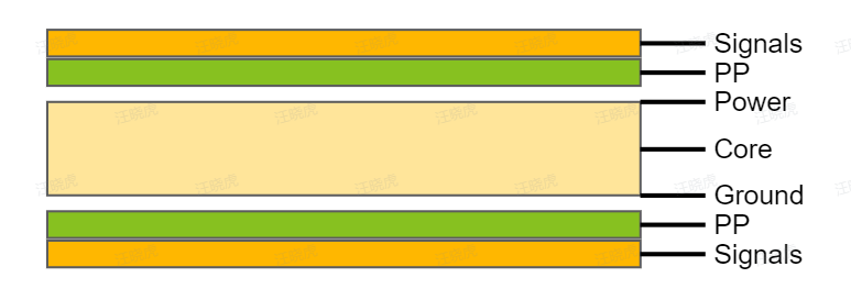
The core of a PCB is sandwiched between conductive copper layers and, in multilayer designs, additional insulating layers called prepregs. Core thickness typically ranges from 0.2 mm to 1.6 mm in standard designs, with 1.6 mm being a common choice for general purpose boards due to its balance of strength and flexibility. The selection depends on the number of layers, the type of electronic components, and the intended use of the board.
From an engineering perspective, core thickness impacts dielectric properties, which govern how signals travel through the board. The dielectric constant of the core material affects signal speed and impedance, especially in high frequency applications. Thicker cores can alter these characteristics, potentially causing signal delays or mismatches if not accounted for in the design phase. Additionally, thermal management is influenced by thickness, as a thicker core may dissipate heat differently compared to a thinner one, affecting the longevity of components.
Manufacturing constraints also play a role. During lamination, the core must withstand heat and pressure without warping, a concern addressed by standards like IPC-6012E, which specifies performance requirements for rigid printed boards. For beginners in PCB design, adhering to such guidelines ensures the core thickness chosen aligns with both design needs and production capabilities.
Key PCB Parameters Beyond Core Thickness
While PCB core thickness is fundamental, several other parameters shape the performance and reliability of a circuit board. Understanding these alongside core thickness builds a comprehensive grasp of PCB terminology and design principles.
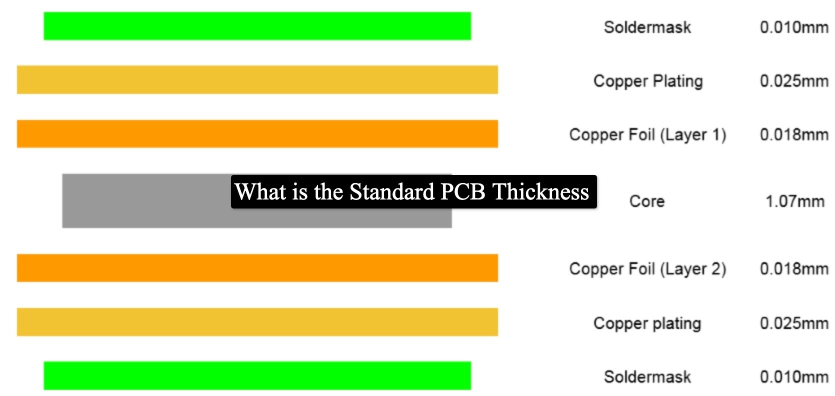
- Copper Thickness: This refers to the thickness of the conductive copper layers on the PCB surface or within internal layers. Common values are 1 oz (35 micrometers) or 2 oz (70 micrometers) per square foot. Thicker copper supports higher current carrying capacity but increases cost and etching complexity.
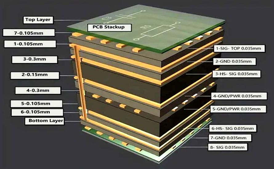
- Board Layers: PCBs can be single sided, double sided, or multilayer. The number of layers affects complexity and cost. More layers allow denser routing of traces but require precise alignment of cores and prepregs during manufacturing.
- Dielectric Material: Beyond the core, the insulating material between layers impacts electrical performance. Materials with different dielectric constants and loss tangents are chosen based on signal requirements, especially for high frequency designs.
- Trace Width and Spacing: These define how electrical signals are routed. Narrower traces save space but may not handle high currents, while wider spacing reduces crosstalk but consumes more board area.
- Via Types and Sizes: Vias are holes that connect different layers electrically. Their size and type, such as through hole or blind vias, influence design density and manufacturing cost.
Each of these parameters interacts with core thickness. For instance, a thicker core might necessitate adjustments in via drilling or trace layout to maintain signal integrity. Familiarity with these aspects through an electronics tutorial or hands on practice equips hobbyists to tackle circuit board design effectively.
Related Reading: PCB Prepreg Thickness: A Designer's Guide to Stackup, Materials, and Performance
Practical Tips for Selecting PCB Core Thickness
Choosing the right PCB core thickness for a project requires balancing design goals with practical constraints. Here are actionable steps for hobbyists venturing into PCB design for beginners.
First, assess the mechanical demands of your application. If the PCB will be mounted in a rugged environment or subject to frequent handling, opt for a thicker core, such as 1.6 mm, to ensure durability. For lightweight or portable devices, a thinner core around 0.8 mm might suffice, reducing weight and material use.
Next, consider the electrical requirements. For basic low frequency circuits common in hobbyist projects, standard core thicknesses work well without special consideration. However, if your design involves high speed signals, consult guidelines like those in IPC-6012E to match core thickness with impedance needs. This standard provides specifications for material selection and performance, helping avoid signal issues.
Also, evaluate the component types you plan to use. Surface mount components often pair better with thinner boards for heat dissipation, while through hole components might require thicker cores for stable mounting. Check component datasheets for any specific board thickness recommendations.
Finally, account for manufacturing capabilities. Not all fabrication processes support extremely thin or thick cores due to equipment limitations. Standard thicknesses like 1.6 mm are widely supported and cost effective for prototyping. When in doubt, start with common values and adjust based on testing and feedback from initial designs.
Related Reading: Choosing the Right PCB Layer Thickness: A Comprehensive Guide
Common Mistakes to Avoid in PCB Core Thickness Selection
Hobbyists new to PCB basics often encounter pitfalls when selecting core thickness. One frequent error is ignoring the impact of thickness on multilayer designs. A core too thick for the number of layers can complicate lamination, leading to delamination or misalignment, issues highlighted in standards like IPC-A-600K for acceptability of printed boards.
Another mistake is overlooking thermal expansion. Different core thicknesses expand at varying rates under heat, potentially causing stress on solder joints or components. This is particularly relevant for boards exposed to temperature fluctuations during operation.
Additionally, beginners sometimes choose non standard thicknesses without verifying manufacturing support. Custom thicknesses may seem ideal for a specific design but can increase costs or lead to delays if outside common production ranges. Sticking to widely accepted values minimizes such risks.
Awareness of these errors, combined with adherence to recognized guidelines, helps ensure a smoother design process. Reviewing standards like IPC-A-600K during planning stages provides clarity on acceptable practices and prevents costly revisions.
Conclusion
Mastering PCB core thickness and related parameters is a foundational step for electronic hobbyists aiming to excel in circuit board design. This parameter influences mechanical strength, electrical performance, and manufacturing feasibility, making it a critical consideration in PCB design for beginners. By understanding PCB materials, terminology, and key factors like copper thickness and layer count, you can make informed choices for your projects. Practical tips, such as matching thickness to application needs and avoiding common mistakes, further enhance design success. As you build your skills through electronics tutorials and hands on experience, these insights will guide you toward creating reliable and efficient PCBs tailored to your goals.
FAQs
Q1: What is PCB core thickness, and why is it important for beginners?
A1: PCB core thickness is the measurement of the central substrate layer in a printed circuit board, providing structural support. For beginners in PCB design, it matters because it affects durability, weight, and electrical performance. Choosing the right thickness ensures components fit properly and signals transmit without issues, forming a key part of learning PCB basics.
Q2: How does PCB core thickness affect circuit board design?
A2: PCB core thickness impacts both mechanical and electrical aspects of circuit board design. Thicker cores offer more strength but add weight, while thinner cores save space but may lack durability. Electrically, thickness influences impedance and signal speed, critical for high frequency designs, making it a vital parameter for hobbyists to understand.
Q3: Which PCB materials influence core thickness selection?
A3: PCB materials, particularly the substrate like fiberglass epoxy composites, play a role in core thickness selection. These materials determine dielectric properties and thermal behavior, affecting how thickness impacts performance. Standards like IPC-6012E guide material choices to ensure compatibility with design needs, helping hobbyists select appropriate thicknesses for their projects.
Q4: What are common mistakes in choosing PCB core thickness for electronics projects?
A4: A common mistake in PCB design for beginners is selecting a core thickness without considering multilayer alignment or thermal expansion, risking delamination or stress on components. Another error is opting for non standard thicknesses that increase costs or delay production. Following standards like IPC-A-600K helps avoid these issues during design.
References
IPC-6012E — Qualification and Performance Specification for Rigid Printed Boards. IPC, 2020.
IPC-A-600K — Acceptability of Printed Boards. IPC, 2020.


