Introduction
Electric engineers often grapple with balancing performance demands and budget constraints in PCB design projects. Embedded components integrate resistors, capacitors, and sometimes active devices directly into the PCB layers, offering potential savings in space and assembly time. This approach supports cost-effective embedded components by reducing surface-mount technology footprint and simplifying routing. However, poor selection can lead to higher manufacturing costs or reliability issues. This article provides a component selection guide focused on embedded components cost analysis, budget PCB design strategies, and optimizing PCB costs through practical engineering decisions. By understanding trade-offs, teams can achieve efficient designs without compromising quality.
What Are Embedded Components and Why Do They Matter?
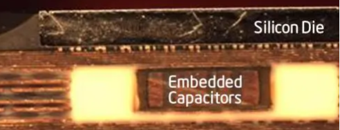
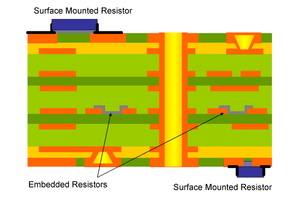
Embedded components are electronic elements buried within the dielectric layers of a printed circuit board, rather than mounted on the surface. Common examples include thin-film resistors formed from resistive inks and capacitors created using high-dielectric-constant materials between conductive planes. This integration minimizes board real estate, which is crucial for compact devices like wearables and IoT modules. In high-volume production, it lowers assembly costs by eliminating pick-and-place operations for those parts.
The relevance stems from shrinking device sizes and rising material expenses. Surface-mount components demand finer pitches, increasing yields risks and inspection times. Embedding shifts costs to the fabrication stage, where economies of scale apply. For budget PCB design, this matters because it enables fewer layers or smaller boards, directly impacting overall expenses. Engineers must weigh initial process complexity against long-term savings.
Technical Principles Behind Embedded Components
Fabrication begins with selecting compatible materials, such as laminates that support cavity formation or ink deposition. For passive resistors, resistive pastes are screen-printed or laser-trimmed on inner layers before lamination. Capacitors form by sandwiching ceramic-filled polymers between copper foils, ensuring precise capacitance values through controlled thickness. Active embedding, like bare dies, requires cavities machined via controlled depth routing or laser ablation, followed by precise placement and encapsulation.
Reliability hinges on thermal expansion matching between components and substrate. Mismatched coefficients of thermal expansion cause delamination during reflow soldering. Standards like IPC-7092 outline design and process implementation for embedded components, specifying inspection criteria and assembly guidelines to mitigate these risks. Electrical performance improves with shorter interconnects, reducing parasitic inductance in high-frequency circuits.
Testing verifies integrity through techniques like time-domain reflectometry for vias connecting to embedded parts. Yield depends on process control, with defects like voids in dielectrics leading to shorts. Troubleshooting involves cross-section analysis to identify lamination issues early in prototyping.
Embedded Components Cost Analysis: Breaking Down the Factors
Optimizing PCB costs starts with dissecting expenses across the supply chain. Non-recurring engineering costs rise due to specialized tooling for cavities or custom inks, but per-unit fabrication amortizes over volume. Material costs include premium dielectrics for capacitors, which can exceed standard FR-4 by a factor tied to dielectric constant needs. Assembly savings emerge from fewer surface-mount parts, cutting stencil and reflow steps.
Volume plays a pivotal role in embedded components cost analysis. Low quantities favor discrete components for simplicity, while high runs benefit from embedding due to reduced bill-of-materials handling. Yield impacts amplify this: a 2% drop from embedding complexity doubles effective costs at scale. Engineers perform break-even calculations by comparing total cost of ownership, factoring prototyping iterations.
Materials
Discrete SMT Impact: Low per part.
Embedded Impact: Higher for specialty dielectrics.
Optimization Tip: Select standard values to minimize custom formulations.
Fabrication
Discrete SMT Impact: Standard layering.
Embedded Impact: Added steps like cavity milling.
Optimization Tip: Batch similar designs to share setup costs.
Assembly
Discrete SMT Impact: High pick-and-place.
Embedded Impact: Reduced SMD count.
Optimization Tip: Embed high-density passives first.
Testing
Discrete SMT Impact: Surface inspection.
Embedded Impact: Buried part verification.
Optimization Tip: Use IPC-6012 qualification for process validation.
Long-term
Discrete SMT Impact: Rework feasible.
Embedded Impact: Field failure risks.
Optimization Tip: Prioritize reliability data from pilots.
Procurement influences through lead times for embedded-capable laminates. Delays inflate holding costs, so aligning with fabricator capabilities early prevents surprises.
Key Factors in Selecting Cost-Effective Embedded Components
Component selection guide begins with functionality requirements. Choose resistors with tolerances matching circuit needs, like 5% for non-critical decoupling versus 1% for precision filters. Capacitors prioritize capacitance density and voltage rating, avoiding over-spec for budget savings. Evaluate supplier data sheets for temperature coefficients, ensuring stability across operating ranges.
Process maturity guides choices: polymer thick-film resistors offer low cost but higher drift, while thin-film provides better stability at premium. For budget PCB design, favor embedded passives over actives unless die size justifies it. Density analysis reveals sweet spots; embedding suits arrays of similar values, not singles.
Environmental factors like humidity demand moisture-resistant materials, per JEDEC J-STD-020 guidelines for reflow sensitivity. High-reliability apps reference IPC-7092 for qualification flows. Simulate parasitics pre-layout to confirm performance without excess margins.
Trade-offs include signal integrity: embedded traces shorten paths but couple noise if layers are thin. Power delivery benefits from planar capacitors reducing loop inductance.
Best Practices for Optimizing PCB Costs with Embedded Components
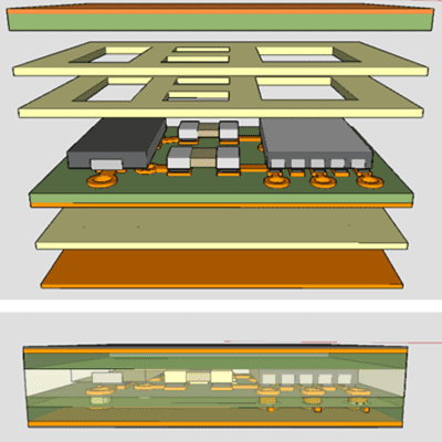
Start designs with stackup planning, allocating inner layers for embedding to avoid outer-layer crowding. Use design rules enforcing minimum clearances around cavities, typically 0.1 mm walls per standards. Prototype small panels to test yield before full runs, iterating on ink formulations if drift exceeds specs.
Collaborate with fabricators on DFM reviews, focusing on lamination pressures for void-free embeds. Standardize component libraries with verified models to speed iterations. For optimizing PCB costs, group embeds by type to streamline processes, like dedicating a core to capacitors.
Troubleshooting low yields involves isolating variables: inspect pre-laminate prints with AOI, and post-process with X-ray for voids. If capacitance varies, recalibrate dielectric thickness controls. Volume scaling tips include qualifying processes to IPC-6012 levels for consistent pricing.
Hybrid approaches embed passives while keeping actives surface-mount for reworkability. Monitor total layer count; embedding often allows HDI reduction.
Common Challenges and Troubleshooting Tips
One frequent issue is thermal management, as embedded parts dissipate less heat. Solution: position high-power embeds near thermal vias or edges. Alignment shifts during lamination plague actives; use fiducials and vision systems for placement.
Cost overruns from low yields trace to poor material matching. Audit CTE data rigorously. Electrical drift post-aging signals ink instability; switch to sputtered films. For budget constraints, de-rate specs slightly if simulations confirm margins.
Field failures manifest as intermittents; bake-out protocols per JEDEC standards prevent popcorn effects.
Conclusion
Selecting cost-effective embedded components demands a holistic view of embedded components cost analysis, from materials to yield. Budget PCB design thrives on informed trade-offs, leveraging mature processes for passives first. By following component selection guides and standards like IPC-7092, engineers optimize PCB costs without sacrificing reliability. Practical troubleshooting ensures smooth transitions to production. Ultimately, embedding empowers compact, economical designs tailored to project needs.
FAQs
Q1: What are the main benefits of cost-effective embedded components in PCB design?
A1: Cost-effective embedded components reduce board size and assembly steps, lowering overall expenses in high-volume runs. They improve signal integrity through shorter paths and enable denser layouts. Success requires careful process control to maintain yields, giving engineers flexibility for compact applications while optimizing PCB costs via strategic selection.
Q2: How do you perform an embedded components cost analysis for budget projects?
A2: Begin with bill-of-materials comparison between SMT and embedded options, factoring fabrication uplifts and assembly savings. Calculate break-even volumes considering NRE and yields. Simulate stackups to quantify layer reductions, and review fabricator quotes for material premiums. This component selection guide ensures data-driven decisions for budget PCB design.
Q3: What factors influence optimizing PCB costs with embedded passives?
A3: Key factors include component density, material choices, and process maturity. High densities favor embedding for economies, while standard tolerances cut custom costs. Yield optimization via standards like IPC-7092 minimizes waste. Volume production amortizes upfront investments effectively, and practical reviews prevent overruns in budget PCB design.
Q4: When should electric engineers avoid embedded components for cost savings?
A4: Avoid embedding in low-volume prototypes due to high NRE without scale benefits. Opt out if rework frequency is high, favoring surface-mount flexibility. Skip for low-density passives where SMT efficiencies prevail, and prioritize discrete parts if tolerances demand precision beyond embedded capabilities. This keeps budget PCB design practical.
References
IPC-7092 - Design and Assembly Process Implementation for Embedded Components. IPC, 2015
IPC-6012E - Qualification and Performance Specification for Rigid Printed Boards. IPC, 2017
JEDEC J-STD-020E - Moisture/Reflow Sensitivity Classification. JEDEC, 2014


