Introduction
Electric engineers designing electronics for extreme environments face unique challenges from temperature extremes, mechanical vibrations, and corrosive conditions. Sectors like aerospace and automotive demand components that maintain performance without failure under prolonged stress. Ceramic PCBs stand out as a solution for high-reliability PCB applications due to their inherent material advantages over traditional organic substrates. These boards excel in ceramic PCB temperature resistance, making them ideal for harsh environment PCB deployments where standard FR-4 materials would degrade. By leveraging ceramic substrates, engineers achieve superior thermal management and structural integrity, ensuring system longevity. This article explores the principles, applications, and best practices for integrating ceramic PCBs into designs targeted at demanding industries.

What Are Ceramic PCBs and Why Do They Matter in Extreme Environments?
Ceramic PCBs use inorganic ceramic materials as the base substrate, typically processed through methods like direct bonded copper or thick-film printing. Unlike organic laminates such as FR-4, ceramics provide exceptional electrical insulation combined with high mechanical strength. This construction supports dense circuitry while withstanding aggressive environmental factors common in aerospace PCB and automotive PCB systems. Harsh environment PCB requirements often exceed the limits of conventional boards, where delamination or trace cracking occurs under thermal cycling. Ceramic options address these issues by offering stability across wide temperature swings and resistance to chemical exposure. Their relevance grows as industries push for compact, power-dense electronics that operate reliably in mission-critical scenarios.
Factory-driven insights reveal that ceramic PCBs align closely with qualification needs for high-reliability PCB production. Engineers specify them when organic alternatives fail reliability projections during accelerated life testing. The material's low moisture absorption prevents issues like conductive anodic filamentation, a common failure mode in humid conditions. Overall, adopting ceramic substrates shifts design paradigms toward robustness, reducing field failures and maintenance costs in extreme deployments.
Technical Principles of Ceramic PCB Performance
The core strength of ceramic PCBs lies in their thermal properties, which directly enhance ceramic PCB temperature resistance. Ceramics exhibit high thermal conductivity, efficiently dissipating heat from power components to prevent hotspots. This capability surpasses organic materials, allowing sustained operation near heat-generating elements without performance loss. Coefficient of thermal expansion (CTE) matching between the ceramic substrate and attached silicon dies minimizes stress during temperature fluctuations, reducing risks of solder joint fatigue. Dielectric breakdown strength remains consistent even under high voltages and elevated temperatures, supporting high-reliability PCB designs.
Mechanical resilience further bolsters their suitability for harsh environment PCB use. Ceramics resist warpage and cracking from vibrations or shocks prevalent in automotive PCB assemblies. The IPC-2221 standard provides design guidelines that emphasize these material interactions for optimal layout and layer stackup. Electrical performance benefits from low signal loss and stable impedance, critical for high-frequency signals in aerospace PCB applications. These principles collectively enable ceramic boards to outperform in thermal shock and humidity tests.
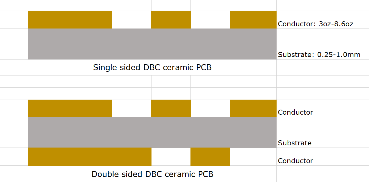
Surface finish and metallization techniques on ceramics ensure reliable adhesion for soldering and wire bonding. Thick-film or thin-film processes create robust conductors that endure repeated thermal cycles without peeling. Insulation resistance holds steady, preventing leakage currents that could compromise system integrity. Factory processes control purity and density to maximize these traits, aligning with performance specifications.
Key Applications: Aerospace and Automotive Sectors
In aerospace PCB designs, ceramic substrates handle the rigors of propulsion systems and avionics exposed to rapid temperature changes and radiation. Engine controls and satellite electronics rely on their ability to maintain functionality from cryogenic lows to combustion highs. Vibration damping properties absorb structural loads during flight, preserving trace integrity over thousands of cycles. High-reliability PCB demands here prioritize zero-defect outcomes, where ceramics deliver proven endurance.
Automotive PCB applications, particularly in electric vehicles and powertrains, benefit similarly from ceramic PCB temperature resistance. Inverter modules and battery management systems face engine bay heat and road vibrations. Harsh environment PCB challenges like oil contamination and thermal runaway are mitigated by the substrate's chemical inertness. Power electronics achieve higher current densities without thermal throttling, extending vehicle range and efficiency.
Defense and oil exploration extend these uses, where remote operations demand unfailing performance. Engineers select ceramics for multilayer configurations supporting complex signal and power routing. Integration with hermetic packaging enhances overall system sealing against moisture ingress.
Best Practices for Designing and Manufacturing Ceramic PCBs
Start design with thermal simulation to map heat paths, optimizing via placement and copper planes for even dissipation. Select substrate thickness based on mechanical loads, balancing rigidity with weight constraints for aerospace PCB use. Trace routing prioritizes wide paths for high currents, adhering to IPC-6012 qualification criteria for conductor integrity. Layer stackups incorporate direct bond copper for multilayer builds, ensuring low thermal resistance.
Manufacturing demands precise control over firing temperatures and metallization to achieve uniform adhesion. Sintering processes densify the ceramic, enhancing fracture toughness for harsh environment PCB reliability. Surface preparation includes plasma cleaning for solderability, followed by controlled reflow profiles. JEDEC thermal standards guide test protocols, verifying performance under simulated extremes.
Quality assurance involves non-destructive inspections like X-ray for voids and acoustic microscopy for delaminations. Accelerated aging tests replicate years of service in weeks, confirming high-reliability PCB margins. Documentation traces material lots for traceability, supporting failure analysis if needed.
Assembly practices focus on low-stress soldering to avoid substrate cracking. Use of lead-free alloys compatible with ceramics ensures compliance without compromising joints. Post-assembly burn-in screens early defects, bolstering field confidence.
Conclusion
Ceramic PCBs transform designs for extreme environments by delivering unmatched ceramic PCB temperature resistance and structural fortitude. Aerospace PCB, automotive PCB, and other high-reliability PCB applications gain from their thermal, mechanical, and electrical superiority. Engineers applying best practices in design, manufacturing, and testing unlock reliable performance where organic boards falter. As demands intensify, ceramics position systems for future-proof operation in harsh environments. Prioritizing these substrates ensures compliance with rigorous standards and elevates overall product dependability.
FAQs
Q1: What makes ceramic PCB temperature resistance superior for harsh environment PCB designs?
A1: Ceramic substrates inherently withstand broader thermal ranges than organic laminates due to high melting points and low degradation. They resist oxidation and phase changes during cycling, maintaining electrical properties. Factory processes ensure density for optimal heat transfer. This suits aerospace PCB and automotive PCB needs under prolonged stress.
Q2: How do ceramic PCBs improve reliability in aerospace PCB applications?
A2: Low CTE mismatch with components reduces solder fatigue from vibration and thermal shock. High dielectric strength supports high-voltage operation in avionics. Mechanical hardness absorbs launch stresses without cracking. Standards-aligned manufacturing verifies endurance for mission-critical use.
Q3: Why choose ceramic PCBs for automotive PCB power electronics?
A3: Superior thermal conductivity dissipates heat from IGBTs and MOSFETs efficiently. Chemical resistance protects against fluids and contaminants. High-reliability PCB traits enable compact modules for EVs. Vibration tolerance ensures longevity in engine bays.
Q4: What standards guide high-reliability PCB qualification using ceramics?
A4: IPC-6012 outlines performance specs for rigid boards in demanding conditions. JEDEC thermal guidelines standardize testing for heat dissipation. These ensure consistency across production. Engineers reference them for design validation.
References
IPC-6012E — Qualification and Performance Specification for Rigid Printed Boards. IPC, 2017
IPC-2221B — Generic Standard on Printed Board Design. IPC, 2012
JEDEC JESD51-12 — Guidelines for Reporting and Using Electronic Package Thermal Information. JEDEC, 2008


