Introduction
Electronic Control Units (ECUs) serve as the brain of modern vehicles, managing everything from engine performance to advanced driver assistance systems. These PCBs operate in engine compartments, underbodies, and other areas exposed to relentless challenges like intense vibrations, elevated temperatures, and moisture intrusion. ECU PCB ruggedization becomes essential to ensure uninterrupted functionality and vehicle safety. Poor design choices can lead to failures such as cracked solder joints, delamination, or corrosion, resulting in costly recalls or safety risks. Engineers must prioritize reliability from the initial design phase, integrating proven strategies tailored to automotive demands. This article outlines structured best practices for creating durable ECU PCBs that withstand harsh environments.
Harsh Environment Challenges Facing ECU PCBs
Automotive environments impose severe stresses on ECU PCBs, starting with mechanical vibrations from road irregularities and engine operation. These forces induce cyclic loading, potentially causing fatigue in traces, vias, and solder joints over time. High temperatures in engine bays accelerate material degradation, leading to issues like laminate warpage or coefficient of thermal expansion mismatches between components and the board. Moisture from road spray, condensation, or humidity exacerbates corrosion on exposed copper and promotes dendritic growth in circuits. Dust, salt, and chemicals further compound these risks, demanding comprehensive protection measures. Understanding these mechanisms guides effective ECU PCB ruggedization efforts.
Material Selection for ECU PCB Ruggedization
Selecting appropriate base materials forms the foundation of ECU PCB ruggedization. Laminates with high glass transition temperature (Tg) resist softening and deformation under elevated thermal loads, maintaining structural integrity. Reinforced FR-4 variants or advanced resins provide better mechanical strength against flexing. Copper foil thickness influences both current handling and vibration resistance, as heavier weights reduce trace flexing. Solder mask and surface finishes must also endure abrasion and oxidation. Adhering to IPC-2221 guidelines for generic design standards ensures material choices align with reliability needs.
Thicker core and prepreg stacks enhance overall board rigidity, minimizing warpage during thermal excursions. Engineers should evaluate dielectric properties to prevent signal integrity loss in high-frequency ECU signals. For extreme conditions, materials compliant with high-reliability classes offer superior performance without compromising manufacturability.
Layout and Routing for Automotive PCB Vibration Resistance
Strategic PCB layout significantly boosts automotive PCB vibration resistance. Positioning mounting holes symmetrically distributes mechanical loads, preventing localized stress concentrations. Wide traces and polygons act as structural beams, reducing deflection under dynamic forces. Vias require anchoring with filled or tented designs to avoid cracking from shear stresses. Component placement favors central areas away from board edges, with tall components secured using corner anchors or epoxy staking. Routing avoids long unsupported spans, incorporating teardrops at pad transitions for strain relief.
Mechanical stiffeners, such as metal frames or embedded supports, further rigidify the assembly. Ground planes on multiple layers dampen resonances and provide uniform stiffness. Simulating board modes during design helps identify and mitigate high-risk frequencies. These practices collectively extend fatigue life in vibrating environments.
High Temperature PCB Design Best Practices
High temperature PCB design demands careful thermal management to prevent failures in ECU applications. Layer stackups should balance copper distribution to control heat flow and minimize hotspots. Thermal vias under power components conduct heat away from sensitive areas, improving dissipation. Clearance and creepage distances increase to accommodate material expansion. Via plating thickness and barrel fill prevent cracking from repeated thermal cycling. Copper balance across layers reduces warpage, ensuring planarity post-reflow.
Component selection focuses on those rated for automotive thermal ranges, with stress-relief patterns in footprints. Heat sinks or thermal pads interface effectively when designed with adequate standoffs. Board thickness influences rigidity and heat spreading, often optimized through iterative analysis. These strategies maintain functionality amid prolonged exposure to engine heat.
Protecting ECU PCBs from Moisture with Conformal Coating
Protecting ECU from moisture relies heavily on conformal coating ECU PCB assemblies. This thin polymeric film encapsulates the board, barring water vapor, salts, and contaminants from reaching circuits. Acrylic coatings offer cost-effective humidity resistance, while silicones excel in thermal flexibility for temperature-variable environments. Urethane types provide abrasion resistance ideal for dusty roads. Application methods like selective spraying or dipping ensure uniform coverage without bridging. Masking critical areas like connectors prevents interference with functionality.
Curing processes must follow manufacturer guidelines to achieve optimal adhesion and thickness. Inspection verifies pinhole-free coverage using dye penetrant or UV methods. For severe exposure, combining coatings with potting compounds adds barrier redundancy. JEDEC J-STD-020 standards guide moisture sensitivity handling during assembly, preventing reflow-induced damage. Proper implementation extends operational life significantly.
Mechanical Reinforcements and Assembly Considerations
Beyond layout, mechanical reinforcements bolster ECU PCB ruggedization. Epoxy underfill secures bottom-terminated components against shear from vibrations. Strain relief loops in flexible traces accommodate flexing without fracture. Board-level shielding cans distribute forces evenly during shocks. Assembly processes emphasize low-stress soldering to avoid initial defects that propagate under environmentals. Fiducials and tooling holes aid precise fixturing during mounting.
Integration with chassis damping reduces transmitted vibrations. Cable strain relief at connectors prevents pull forces from stressing PCB edges. These holistic measures create a robust system-level design.
Qualification Testing for Harsh Environment Reliability
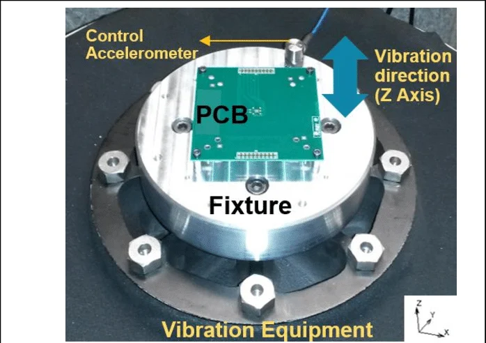
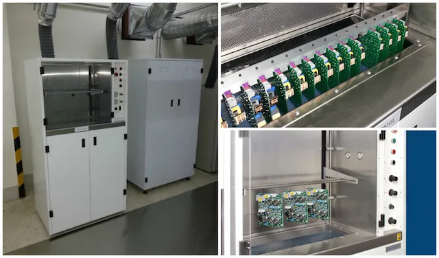
Validation through environmental testing confirms design robustness. Vibration profiles simulate road and engine spectra, monitoring for resonance-induced failures. Thermal cycling exposes boards to rapid temperature swings, assessing expansion compatibility. Humidity tests combined with bias reveal corrosion vulnerabilities. IPC-6012 specifications outline qualification for rigid boards in high-reliability applications, including Class 3 criteria for continuous operation.
Accelerated life testing extrapolates field performance, guiding iterations. Failure analysis pinpoints root causes, refining future designs. Documentation of test data supports compliance and traceability.
Conclusion
Designing ECU PCBs for harsh environments requires a multifaceted approach encompassing material selection, layout optimization, protective coatings, and rigorous testing. Automotive PCB vibration resistance demands mechanical reinforcements and strategic routing, while high temperature PCB design focuses on thermal management. Conformal coating ECU PCB effectively shields against moisture, enhancing overall durability. By following these best practices and leveraging standards like IPC-2221, JEDEC J-STD-020, and IPC-6012, engineers achieve reliable performance that safeguards vehicle safety and longevity. Prioritizing these principles from concept to production minimizes risks and maximizes value.
FAQs
Q1: What are key strategies for ECU PCB ruggedization in automotive applications?
A1: ECU PCB ruggedization involves high Tg materials, reinforced layouts, and conformal coatings to combat vibration, heat, and moisture. Symmetric mounting holes and via anchoring enhance mechanical strength. Thermal vias and balanced stackups manage heat dissipation. Testing per industry standards verifies endurance. These steps ensure long-term reliability without over-engineering.
Q2: How does automotive PCB vibration resistance improve with design choices?
A2: Automotive PCB vibration resistance relies on wide traces, stiffeners, and component staking to minimize flexing and fatigue. Ground planes dampen vibrations, while teardrops prevent trace cracks. Avoiding edge-mounted tall parts reduces leverage points. Simulations identify risky modes early. Proper assembly underfill secures joints, extending life under cyclic loads.
Q3: Why is conformal coating essential for high temperature PCB design in ECUs?
A3: Conformal coating ECU PCB provides thermal flexibility alongside moisture protection, crucial for high temperature PCB design. Silicones maintain integrity across wide ranges, preventing delamination. Uniform application avoids hotspots. It complements thermal vias and heat sinks. Standards guide thickness for optimal performance in engine bays.
Q4: What methods effectively protect ECU from moisture during operation?
A4: Protecting ECU from moisture uses conformal coatings like urethane for chemical resistance and parylene for vapor barriers. Selective application covers circuits while exposing connectors. Combined with sealed enclosures, it blocks road splash and humidity. Handling per moisture sensitivity standards prevents assembly issues. Regular inspection maintains efficacy.
References
IPC-2221 — Generic Standard on Printed Board Design. IPC, 2012
JEDEC J-STD-020E — Moisture/Reflow Sensitivity Classification of Nonhermetic Surface Mount Devices. JEDEC, 2014
IPC-6012E — Qualification and Performance Specification for Rigid Printed Boards. IPC, 2017