Introduction
The Robot Operating System (ROS) stands as a pivotal middleware framework in modern robotics, facilitating the development of complex robotic systems through modular software components. Control printed circuit boards (PCBs), often referred to as ROS PCBs, form the essential hardware layer that interfaces ROS software with physical robotic elements such as sensors and actuators. These embedded systems must manage real-time data flows, diverse communication protocols, and power demands unique to robotics applications. Electric engineers designing ROS PCBs face challenges in balancing computational performance, signal integrity, and compactness within constrained form factors. Effective integration ensures low-latency sensor data processing and reliable operation in dynamic environments. This article delves into the principles, design strategies, and best practices for crafting high-performance ROS PCBs.
What Is ROS and Why ROS PCBs Matter
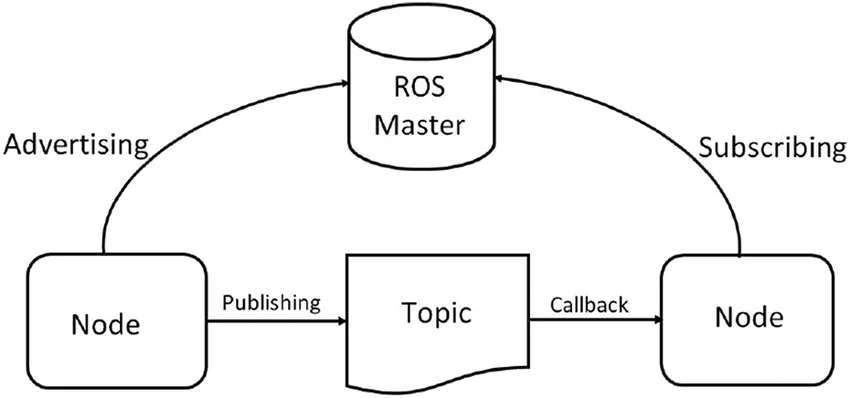
ROS functions as an open-source middleware suite that provides standardized tools for robotics software development, including hardware abstraction, device drivers, and message-passing paradigms. At its core, ROS employs a publish-subscribe model where nodes exchange data via topics, services, and actions, making it ideal for distributed embedded systems in robots. ROS PCBs are specialized boards that host microcontrollers or single-board computers capable of running ROS nodes, thereby bridging software middleware with hardware peripherals. Their importance stems from the need to support high-throughput sensor data processing from cameras, lidars, and IMUs, while adhering to robotics software constraints like deterministic timing.
In industrial and research robotics, ROS PCBs enable scalable architectures where multiple boards communicate over networks, reducing wiring complexity and enhancing modularity. Poorly designed PCBs can introduce latency, electromagnetic interference, or power instability, compromising ROS performance and robotic reliability. Engineers must prioritize ROS PCB design to accommodate evolving standards in embedded systems, ensuring compatibility with ROS 1 and the more advanced ROS 2 features like DDS for real-time communication. Ultimately, robust ROS PCBs empower engineers to prototype and deploy robots efficiently.
Key Technical Principles in ROS PCB Design
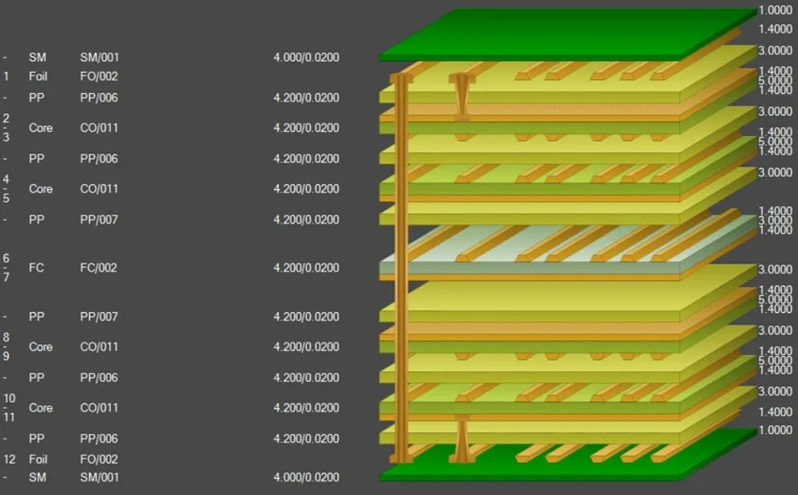
ROS integration demands PCBs that support processor-intensive tasks alongside precise analog and digital interfaces. Core principles include multilayer stackups to segregate power, ground, and signal planes, minimizing crosstalk in high-speed communication protocols such as Ethernet for ROS topic exchanges. Embedded systems running ROS require stable clock distribution to maintain synchronization across nodes, with crystal oscillators and PLLs tuned for middleware timing requirements. Sensor data processing involves high-resolution ADCs and FPGAs to handle raw inputs from multiple channels without bottlenecks.
Power integrity forms another pillar, as ROS nodes on embedded systems draw variable currents during computation spikes from robotics software algorithms. Designers implement multiphase DC-DC converters and low-ESR capacitors to sustain clean rails for core logic, analog sensors, and motor drivers. Thermal management principles dictate via-in-pad cooling and copper pours under heat-generating ICs, preventing throttling in continuous operation. Adherence to IPC-6012E ensures qualification for rigid printed boards used in ROS control applications, verifying performance under vibration and temperature cycles typical in robotics.
Signal integrity analysis guides trace routing, with impedance-controlled lines for USB, UART, and CAN buses that carry ROS messages in lower-bandwidth setups. Differential pairs for LVDS or MIPI interfaces support high-fidelity sensor data processing from vision systems. Ground plane stitching vias suppress common-mode noise, while length-matched routing preserves timing for multi-node synchronization. These principles collectively enable ROS PCBs to deliver the determinism essential for robotics software execution.
Essential Hardware Components for ROS-Compatible PCBs
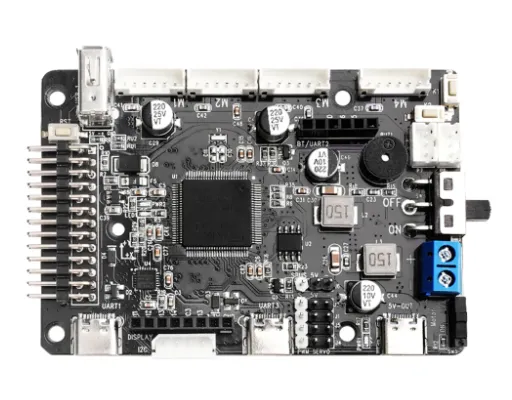
Selecting components for ROS PCBs begins with processors suited for running lightweight ROS distributions on resource-constrained embedded systems. ARM-based SoCs with integrated GPUs handle middleware overhead, supporting ROS packages for navigation and perception. Communication protocols necessitate PHY chips for Gigabit Ethernet, enabling ROS 2's DDS middleware over UDP, alongside CAN controllers for actuator feedback loops.
Sensor interfaces dominate ROS PCB real estate, featuring multiplexed ADC arrays for analog signals from encoders and force sensors, processed via DMA to minimize CPU intervention. GPIO expanders and I2C hubs connect clusters of IMUs and environmental sensors, streamlining data aggregation for ROS topics. Power management ICs provide sequenced rails, such as 3.3V for logic, 5V for USB, and higher voltages for servo drivers, with PMICs offering protection against inrush currents in robotic deployments.
Memory subsystems include DDR SDRAM for ROS node buffering and eMMC for storing robotics software packages, with error-correcting codes to ensure data integrity during sensor fusion. Fuses and supervisors monitor supply voltages, triggering safe shutdowns if anomalies arise from middleware-induced overloads. These components, integrated thoughtfully, form the foundation for scalable ROS embedded systems.
PCB Layout Best Practices for Optimal ROS Integration
Layout strategies for ROS PCBs emphasize partitioning to isolate noisy digital sections from sensitive analog paths for sensor data processing. Place high-speed Ethernet magnetics near board edges, routing 100-ohm differential pairs with minimal vias to preserve ROS communication protocol integrity. Power planes should underlay processor and memory blocks, with decap arrays spaced at lambda/20 intervals to quell resonances from robotics software bursts.
Decoupling and filtering networks suppress EMI, using ferrite beads on I/O lines and shielding cans over RF-prone areas. For thermal reliability, engineers incorporate heat pipes or exposed pads connected to chassis grounds, dissipating heat from continuous sensor data processing. IPC-A-600K guidelines for acceptability ensure visual and electrical inspections catch defects like insufficient solder fillet or delamination post-fabrication.
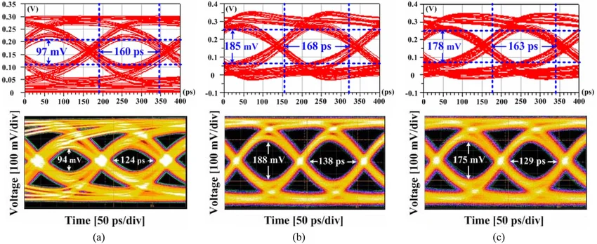
Routing hierarchies prioritize critical nets: clock to processor first, then data buses, followed by low-speed controls. Blind and buried vias in high-density areas save surface space for connectors, facilitating modular robot stacking. Post-layout simulations verify eye diagrams for communication protocols, confirming margin against jitter in ROS pub-sub cycles. These practices yield ROS PCBs resilient to the vibrations and EMI of mobile robotics.
Common Challenges and Troubleshooting in ROS PCB Design
Engineers often encounter latency spikes in ROS PCBs due to inadequate buffering in sensor data processing pipelines, addressed by increasing FIFO depths and optimizing DMA configurations. Signal reflections on long traces degrade communication protocols, mitigated by series terminations and TDR validation during prototyping. Power supply ripple from motor commutation couples into analog lines, requiring LC filters and star-point grounding schemes.
EMI compliance poses hurdles in dense layouts, where ROS middleware traffic generates broadband noise; solutions include spread-spectrum clocks and grounded guard traces. Overheating during intensive robotics software tasks leads to thermal runaway, countered by active cooling headers and junction temperature monitoring. Troubleshooting involves boundary scan for assembly verification and protocol analyzers to debug ROS message flows. J-STD-001G standards guide hand-soldering and rework for prototypes, ensuring joint reliability.
Firmware-hardware mismatches, such as mismatched baud rates on UART for ROS serial bridges, cause data corruption; iterative flashing and logging resolve these. Mechanical stresses from robot mounting warp boards, necessitating conformal coatings per IPC specifications. Systematic DFT insertion aids diagnosis, streamlining iterations toward production-ready ROS embedded systems.
Conclusion
Designing ROS PCBs for Robot Operating System integration synthesizes hardware prowess with middleware demands, yielding embedded systems primed for advanced robotics. Key to success lies in mastering signal integrity, power distribution, and thermal control while supporting diverse communication protocols and sensor data processing. By following structured layout principles and industry standards, electric engineers can deliver reliable, high-performance boards that accelerate robotic development. Future iterations will leverage denser integrations and edge AI, further elevating ROS PCB roles. Prioritizing these elements ensures robust, scalable solutions for the next generation of intelligent machines.
FAQs
Q1: What is a ROS PCB and its role in embedded systems?
A1: A ROS PCB is a custom printed circuit board optimized for hosting Robot Operating System nodes within robotics applications. It integrates processors, interfaces, and power circuits to enable seamless middleware execution on embedded systems. These boards handle sensor data processing and communication protocols, ensuring low-latency operation critical for real-time control. Proper design enhances modularity and reliability in robotic platforms.
Q2: Why are communication protocols crucial in ROS PCB design?
A2: Communication protocols like Ethernet, CAN, and UART form the backbone of ROS topic exchanges on PCBs. They enable efficient data sharing between nodes in distributed robotics software architectures. Engineers must route these with controlled impedance to avoid packet loss or jitter, vital for middleware performance. Robust protocol support minimizes latency in multi-board setups.
Q3: How do you optimize sensor data processing on ROS PCBs?
A3: Optimization involves high-speed ADCs, DMA channels, and FPGA preprocessing on ROS PCBs to manage high-volume inputs from sensors. Strategic placement reduces noise coupling, while buffering prevents middleware bottlenecks. Power-optimized rails sustain continuous operation, aligning with robotics software needs. Validation through data logging confirms throughput meets real-time constraints.
Q4: What best practices ensure signal integrity in ROS embedded systems?
A4: Prioritize impedance matching, minimal vias, and ground plane returns for high-speed nets in ROS embedded systems. Decoupling capacitors at loads suppress noise from communication protocols. Simulations predict eye openings, guiding layout refinements. Compliance with standards verifies performance under operational stresses, safeguarding ROS reliability.
References
IPC-6012E — Qualification and Performance Specification for Rigid Printed Boards. IPC, 2018
IPC-A-600K — Acceptability of Printed Boards. IPC, 2020
J-STD-001G — Requirements for Soldered Electrical and Electronic Assemblies. IPC, 2018