Introduction
Assembling a printed circuit board (PCB) is a critical skill for manufacturing engineers in the electronics industry. This process involves mounting components onto a PCB to create functional electronic devices, requiring precision, technical knowledge, and adherence to industry standards. Whether working on prototypes or mass production, understanding the tools like the soldering iron for manual soldering and materials such as solder wire is essential. This guide provides a comprehensive overview of PCB assembly, focusing on practical techniques, best practices, and key considerations for engineers. From preparing the workspace to mastering soldering methods, this article equips you with the knowledge to achieve reliable results. Let’s explore the fundamental steps and principles behind successful PCB assembly.
What Is PCB Assembly and Why It Matters
PCB assembly is the process of attaching electronic components to a printed circuit board to form a complete circuit. It transforms a bare board into a functional unit capable of powering devices, from consumer electronics to industrial equipment. For manufacturing engineers, PCB assembly is a cornerstone of production, directly impacting product reliability, performance, and cost efficiency.
The importance of proper assembly cannot be overstated. Poor soldering techniques or incorrect component placement can lead to circuit failures, short circuits, or thermal issues. In high stakes applications like medical or aerospace systems, such errors could have severe consequences. By mastering assembly processes and using tools like the soldering iron for manual soldering, engineers ensure consistent quality. Additionally, understanding materials like solder wire helps in achieving strong, durable connections that withstand operational stresses.
Technical Principles of PCB Assembly
Understanding the PCB Layout
Before assembly begins, engineers must familiarize themselves with the PCB layout. This includes identifying component placements, solder pads, and traces as per the design schematic. Standards such as IPC-A-600K provide guidelines for acceptable board conditions, ensuring the bare PCB is free from defects like scratches or contamination before assembly starts.
Component Types and Placement
PCBs typically host two types of components: through hole and surface mount. Through hole components have leads inserted into drilled holes, while surface mount devices sit directly on the board’s surface. Correct placement is crucial, as misalignment can disrupt electrical connections. Following standards like IPC-7351B aids in understanding land pattern designs for accurate positioning.
Soldering Fundamentals
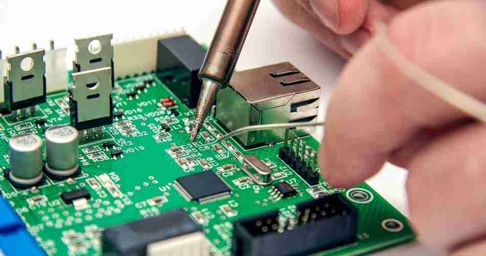
Soldering forms the backbone of PCBA assembly. It involves melting solder wire, a metal alloy, to create a permanent bond between components and the PCB. A soldering iron for manual soldering heats the solder wire, allowing it to flow into joints. The process requires controlling temperature to avoid damaging components or the board. Standards such as IPC J-STD-001H outline requirements for soldered electrical and electronic assemblies, ensuring joint reliability.
Temperature control is vital. Overheating can degrade components, while insufficient heat results in weak joints. Flux, often integrated into solder wire, cleans surfaces during soldering, enhancing adhesion. Engineers must select appropriate solder wire compositions, typically lead free alloys, to comply with environmental regulations and industry norms.
Assembly Workflow
The assembly process follows a logical sequence. First, prepare the PCB by cleaning it to remove contaminants. Next, place components according to the design. For manual assembly, secure through hole components first, followed by surface mount parts if mixed technology is used. Soldering comes next, using a soldering iron for manual soldering to create robust connections. Finally, inspect the board for defects, adhering to guidelines in IPC-A-610H for acceptability criteria.
Practical Solutions and Best Practices for PCB Assembly
Setting Up the Workspace
A well organized workspace boosts efficiency and safety. Ensure adequate lighting to spot small components and solder joints. Use an antistatic mat and wrist strap to prevent electrostatic discharge, which can damage sensitive parts. Keep the soldering iron for manual soldering on a stable holder when not in use to avoid burns or fires. Maintain a clean area free of clutter to focus on the task.
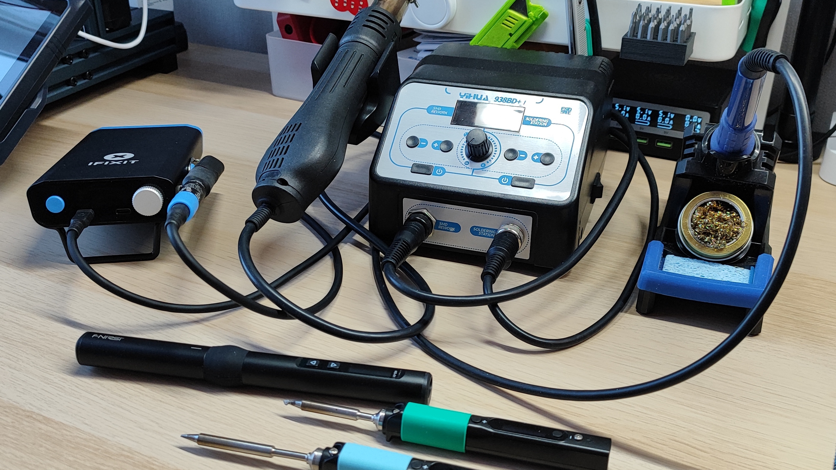
Selecting the Right Tools and Materials
Choosing the correct soldering iron for manual soldering is critical. Opt for a model with adjustable temperature settings to match different components and board types. A fine tip works best for precision tasks on small pads. Solder wire should be of high quality, often with a rosin core flux to aid in soldering. Refer to IPC J-STD-004B for flux classification and selection to ensure compatibility with your materials.
Other essential tools include tweezers for component handling, a magnifying glass for inspection, and desoldering equipment for rework. A fume extractor is recommended to remove harmful vapors produced during soldering with solder wire. Following safety protocols protects both the engineer and the equipment.
Step by Step Soldering Technique
- Heat the soldering iron to the appropriate temperature, typically guided by component specifications and board materials.
- Clean the iron tip with a damp sponge or brass wire cleaner to remove oxidation.
- Apply a thin layer of solder wire to the tip, known as tinning, to improve heat transfer.
- Position the component on the fast turn PCB, ensuring alignment with solder pads.
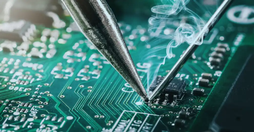
- Touch the iron tip to the pad and component lead simultaneously, then introduce solder wire to the joint.
- Remove the solder wire first, followed by the iron, allowing the joint to cool naturally.
- Inspect the joint for a shiny, concave appearance, indicating a good connection per IPC-A-610H standards.
Avoid excessive solder, which can cause bridging between pads, and ensure the joint cools without movement to prevent cracking.
Handling Common Challenges
Manufacturing engineers often face issues like cold solder joints, where the connection appears dull and weak due to insufficient heat. Reheating the joint with the soldering iron for manual soldering and adding fresh solder wire can resolve this. Another challenge is component overheating, which can be mitigated by using a heat sink or working in short bursts.
For mixed technology boards, prioritize soldering surface mount components before through hole parts to avoid thermal stress. If desoldering is needed, use a desoldering pump or braid, following safety guidelines to protect the board. Standards like IPC-7711/7721C offer detailed rework and repair procedures for such scenarios.
Inspection and Quality Control
Post assembly inspection ensures reliability. Visually check solder joints for uniformity and defects using criteria from IPC-A-610H. Use a multimeter to test continuity and confirm electrical connections. For critical applications, consider advanced methods like X ray inspection to detect hidden flaws. Adhering to quality standards minimizes failures in the field, safeguarding end user trust.
Troubleshooting Insights for PCB Assembly
Manufacturing engineers often encounter unexpected issues during PCB assembly. One common problem is solder bridging, where excess solder wire connects adjacent pads, causing shorts. This can be fixed by using a desoldering braid to remove the excess material. Another issue is lifted pads, often due to excessive heat from the soldering iron for manual soldering. Preventing this requires precise temperature control and minimal contact time.
Component misalignment during placement can also disrupt assembly. Using a stencil or fixture can aid in accurate positioning, especially for surface mount parts. If a component fails post soldering, test surrounding connections to isolate the fault. Rework should follow IPC-7711/7721C guidelines to avoid further damage. These practical insights, drawn from assembly experience, help engineers address challenges efficiently.
Conclusion
Assembling a PCB board is a meticulous process that demands technical skill and attention to detail. From understanding the layout to mastering soldering with a soldering iron for manual soldering, manufacturing engineers play a pivotal role in ensuring quality. Selecting the right solder wire and following industry standards like IPC J-STD-001H guarantees reliable connections. By implementing best practices and troubleshooting effectively, engineers can overcome common assembly challenges. This guide serves as a foundation for achieving consistent, high quality PCB assembly outcomes in diverse applications.
FAQs
Q1: What is the best soldering iron for manual soldering of PCB boards?
A1: For manual soldering of PCB boards, a soldering iron with adjustable temperature control is ideal. It allows engineers to match the heat to specific components and board materials, preventing damage. A fine tip ensures precision on small pads. Following standards like IPC J-STD-001H helps in selecting equipment that meets assembly requirements for consistent, reliable results.
Q2: How do I choose the right solder wire for PCB assembly?
A2: Selecting solder wire involves considering alloy composition, often lead free for environmental compliance, and flux type. Rosin core flux in solder wire aids in cleaning surfaces during soldering. Refer to IPC J-STD-004B for flux classification to ensure compatibility. Opt for a diameter suitable for the component size to control solder application effectively.
Q3: What are common mistakes when using a soldering iron for manual soldering?
A3: Common mistakes include overheating components with the soldering iron for manual soldering, leading to damage, and using insufficient heat, causing weak joints. Not cleaning the iron tip can result in poor heat transfer. Avoid moving components before the solder cools, as it risks cracking. Adhering to IPC-A-610H standards helps identify and prevent such errors.
Q4: How can I ensure quality solder joints with solder wire?
A4: To ensure quality solder joints, use high quality solder wire with appropriate flux. Heat both the pad and component lead evenly before applying solder. Inspect joints for a shiny, concave shape as per IPC-A-610H criteria. Avoid excess solder to prevent bridging. Proper technique and regular inspection are key to reliable connections.
References
IPC-A-600K — Acceptability of Printed Boards. IPC, 2020.
IPC-7351B — Generic Requirements for Surface Mount Design and Land Pattern Standard. IPC, 2010.
IPC J-STD-001H — Requirements for Soldered Electrical and Electronic Assemblies. IPC, 2021.
IPC J-STD-004B — Requirements for Soldering Fluxes. IPC, 2011.
IPC-A-610H — Acceptability of Electronic Assemblies. IPC, 2021.
IPC-7711/7721C — Rework, Modification and Repair of Electronic Assemblies. IPC, 2021.


