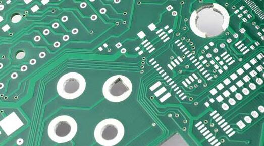
What Are Plated Through-Holes (PTH) and Why Are They Crucial?
Plated through-holes (PTHs) are small, conductive conduits extending through the layers of a printed circuit board. These holes are coated with a conductive material, typically copper, to establish electrical connections between different layers of the PCB. Beyond their role in electrical pathways, PTHs also serve as secure mounting points for traditional through-hole components such as resistors, capacitors, and various connectors. Their integrity is fundamental for signal transmission and the overall intended functionality of the circuit board.
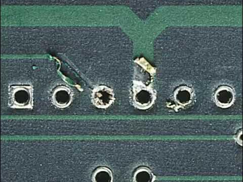
Understanding PTH Vulnerabilities
When a PTH suffers damage—whether from improper handling, aggressive component removal, or manufacturing flaws—it can interrupt the crucial electrical connection, leading to circuit failure. Common forms of damage include cracks in the conductive barrel lining, lifted solder pads, or complete disconnections to internal layers. Repairing these defects often proves more economical than replacing an entire PCB, particularly for complex or high-value boards, making the PTH repair process a valuable skill.
What Causes Plated Through-Hole Damage?
Before delving into the methods for PTH repair, it's beneficial to understand the typical origins of such damage. Recognizing these root causes can help implement preventive measures and avoid future issues.
Common Reasons for PTH Failure
● Improper Component Removal: Applying excessive heat or force during desoldering can crack the PTH barrel or cause the surrounding solder pad to lift from the board.
● Mechanical Stress: Physical impacts, like dropping a PCB, or undue pressure during assembly can lead to structural damage within the holes.
● Thermal Cycling: Repeated exposure to heating and cooling cycles, particularly during multiple soldering operations, can gradually weaken the PTH structure.
● Manufacturing Imperfections: Substandard plating quality or insufficient copper thickness during the PCB fabrication process can result in inherently weak PTHs that are prone to failure under stress.
Being aware of these factors can promote more cautious handling of PCBs during both assembly and rework procedures.
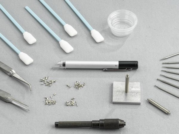
What Tools and Materials Are Needed for PTH Repair?
To effectively repair a damaged plated through-hole, having the correct tools and materials is paramount. A dedicated PTH repair kit often provides the most convenient starting point, as these kits typically contain all the necessary items for the job.
Essential Kit Components for PTH Repair
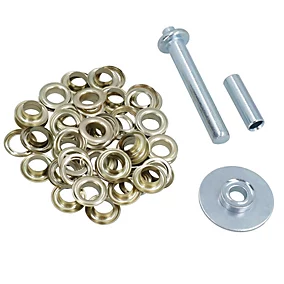
● Eyelets or Funnelets: These are small tubes, typically copper or tin-plated, used to reconstruct the conductive path within a damaged PTH. They are available in various sizes to match different hole diameters.
● Precision Drill and Bits: A micro-drill set (e.g., 0.5mm to 1.5mm) is used to meticulously clear out damaged material from the hole or slightly enlarge it for eyelet insertion.
● Eyelet Setting Tool: A specialized tool designed to flare or crimp the eyelet securely into place, ensuring a stable mechanical connection.
● Soldering Station: A fine-tip soldering iron (around 25-40 watts) and high-quality solder are needed to secure the eyelet and re-establish trace connections.
● Desoldering Tools: A desoldering pump or wick is essential for removing old solder from the damaged area before repair.
● Conductive Epoxy or Adhesive: Used for securing eyelets or repairing localized damage to the board's substrate if necessary.
● Magnification Device: A magnifying glass or microscope is vital for detailed inspection of small PTHs and to ensure precision during the repair process.
● Cleaning Supplies: Isopropyl alcohol and a small brush are needed for post-repair cleanup to remove flux residue.
● Multimeter: An essential tool for testing continuity and verifying that the repair has successfully restored the electrical connection.
Many of these items are standard inclusions in a PTH repair kit, specifically curated for tasks such as eyelet repair. If you plan a DIY PTH repair, ensure you have these fundamental items to avoid interruptions.
How Do You Execute the PTH Repair Process Step-by-Step?
With your tools at the ready, let's proceed through the comprehensive PTH repair process. This guide focuses on eyelet repair, a widely accepted method suitable for both professional and amateur projects. Following these steps precisely will ensure a reliable and lasting fix.
1. Assessing the Extent of Damage
Begin by meticulously inspecting the compromised PTH using a magnifying glass or microscope. Look for hairline cracks in the copper barrel, evidence of lifted pads, or any breaks in connections to internal layers. Use a multimeter to perform a continuity test between the top and bottom layers of the PCB. A lack of connection, or an unusually high resistance reading (e.g., exceeding 0.1 ohms for a typical PTH), signals that a repair is necessary.
2. Preparing and Cleaning the Damaged Area
Carefully remove any debris, residual solder, or compromised material from the PTH. Use a desoldering pump or wick to completely clear the hole of solder. If the hole is blocked or the barrel is cracked, cautiously drill out the damaged material using a micro drill bit that is slightly larger than the original hole's diameter (for example, a 0.8mm bit for a 0.6mm hole). Take extreme care not to damage surrounding traces or pads. Afterward, clean the area thoroughly with isopropyl alcohol to remove any flux residue or dust.
3. Selecting the Correct Eyelet
From your PTH repair kit, choose an eyelet that precisely matches the cleaned hole's diameter and the PCB's thickness. Eyelets are typically available in diameters ranging from 0.5mm to 2.0mm and with various flange styles, such as flat or funnel-shaped, to suit different clearance requirements. For instance, a flat flange eyelet is ideal for low-profile repairs where components will sit close to the board surface. Ensure the eyelet's length corresponds to the PCB's thickness (e.g., 1.6mm for a standard board) to prevent undesirable protrusion.
4. Inserting and Securing the Eyelet
Insert the chosen eyelet into the prepared hole from the component side of the PCB, ensuring its flange lies flat against the board surface. Use a specialized setting tool to gently flare or crimp the opposite end of the eyelet on the reverse side of the board. This action firmly secures the eyelet and establishes a solid mechanical connection. Apply steady, gentle pressure to avoid cracking the surrounding PCB material.
5. Soldering the Eyelet
Using a fine-tip soldering iron, apply solder to both ends of the eyelet where it meets the PCB pads. Use only enough solder to create a smooth, shiny fillet, avoiding excessive blobs that could impede component insertion. If the PTH connects to internal layers, verify that the solder flows evenly to maintain comprehensive conductivity. Allow the repaired area to cool naturally to mitigate thermal stress.
6. Verifying the Repair
Once the soldering is complete and the joint has cooled, re-test for continuity using a multimeter. You should observe a very low resistance reading (approaching 0 ohms), which confirms a successful connection. If the PTH is part of a signal path, consider testing the entire board under operational conditions to confirm signal integrity. For example, in high-frequency circuits, impedance should remain within acceptable limits (e.g., 50 ohms for many RF applications).
7. Final Cleaning and Inspection
Conclude the repair by cleaning the area with isopropyl alcohol and a brush to remove any residual flux or contaminants. Conduct a final inspection under magnification to ensure there are no cold solder joints, cracks, or other defects. If all checks are satisfactory, your damaged PTH repair is complete!
Can You Perform DIY PTH Repair? Tips for Hobbyists
For hobbyists attempting a DIY PTH repair without a professional kit, good results are still achievable using basic tools and materials. Here are some practical recommendations for success.
Practical Advice for Amateur Repair
● Alternative Materials: If you lack specialized eyelets, thin copper wires or small pieces of copper tubing can sometimes serve as a temporary substitute. Strip a fine wire, thread it through the hole, and then bend or flare the ends to mimic an eyelet flange before soldering.
● Practice on Scrap: Before working on a valuable PCB, practice your repair technique on a scrap board. This will help you become comfortable with drilling, eyelet insertion, and soldering in confined spaces.
● Manage Heat Carefully: Use a low-wattage soldering iron and work quickly to prevent overheating the PCB, which can lead to delamination of layers or damage to nearby components.
● Always Verify Connections: After any repair, always use a multimeter to test for continuity. A poor connection might seem to work initially but could fail under load or over time.
While DIY PTH repair can be a cost-saving measure, investing in a proper PTH repair kit is generally recommended for consistent and reliable outcomes, especially for critical projects.
How Can You Prevent Future PTH Damage?
While repairing a damaged PTH is a valuable skill, preventing damage in the first place is even more advantageous. Adopting best practices for handling and assembling PCBs can significantly extend their lifespan.
Best Practices for PCB Longevity
● Correct Desoldering Techniques: Always use a desoldering pump or wick for component removal, and avoid excessive heat (keep soldering iron temperatures typically below 300°C for most boards).
● Gentle Handling: Store types of PCBs in protective casings or anti-static bags to shield them from physical damage, such as drops or scratches.
● Assembly Support: Employ a PCB holder or vise during soldering and assembly to prevent board flexing, which can stress PTHs.
● Pre-Assembly Inspection: Before populating new boards with components, inspect them thoroughly for manufacturing flaws like thin plating or misaligned holes.
Advanced Considerations for PTH Repair
For engineers working with the high-frequency PCB, additional factors must be considered during a damaged PTH repair. The repair must meticulously maintain the board’s original electrical characteristics, such as impedance, to prevent signal degradation. A poorly repaired PTH in an RF circuit, for instance, could introduce undesirable capacitance or inductance, altering the impedance from a standard 50 ohms and leading to signal reflections.
Furthermore, if the PTH connects to internal layers, ensure that the chosen eyelet or repair method fully restores this connection without creating any short circuits. In complex scenarios, using a conductive epoxy in conjunction with an eyelet can help bridge internal layer connections if soldering alone is insufficient. For mission-critical applications, always consult industry standards like IPC-7711/7721 for advanced repair guidelines.
Conclusion: Confidently Restore Your PCBs
The task of repairing a damaged plated through-hole should not be daunting. With the appropriate tools, such as a specialized PTH repair kit, and a comprehensive understanding of the PTH repair process, you can successfully restore the functionality of your compromised PCBs, thereby avoiding expensive replacements. Whether you opt for established eyelet repair techniques or explore more improvisational DIY methods, the steps outlined in this guide will equip you to tackle damaged PTH repair effectively.
By integrating best practices into your routine and taking proactive preventive measures, you can significantly reduce the likelihood of future damage, keeping your projects on schedule. Always remember that precision and patience are your key allies in achieving a successful repair. So, gather your equipment, meticulously inspect your board, and begin salvaging your PCBs today!


