Introduction
Automotive infotainment systems integrate multimedia interfaces, navigation, connectivity modules, and user controls into vehicle dashboards. These systems rely on printed circuit boards (PCBs) to handle high-speed data transmission, power distribution, and sensor integration under harsh environmental conditions. Selecting the right PCB design software becomes critical for electrical engineers tasked with creating reliable layouts that meet stringent automotive requirements. This comparison evaluates Altium Designer automotive PCB capabilities, Eagle PCB infotainment features, and KiCad PCB design review aspects to identify the best PCB design software automotive professionals. Factors such as signal integrity tools, multilayer support, and design rule checks (DRC) play key roles in ensuring compliance and performance. Engineers must balance advanced functionality with usability for efficient workflows in complex infotainment projects.
What Are Automotive Infotainment PCBs and Why Do They Matter?
Automotive infotainment PCBs serve as the backbone for head units that process audio, video, Bluetooth, Wi-Fi, and touchscreen inputs. These boards manage mixed-signal environments where digital processors coexist with analog audio amplifiers and RF modules. Reliability matters because infotainment systems operate in temperature extremes from -40°C to 125°C, vibration, and humidity, demanding high-reliability fabrication per IPC Class 3 standards. Poor design can lead to electromagnetic interference (EMI) disrupting CAN bus communications or signal degradation in LVDS video lines. Effective software enables engineers to implement controlled impedance stackups and thermal reliefs early. Ultimately, optimal PCB design software automotive choice accelerates time-to-market while minimizing field failures in vehicles.
Infotainment evolution toward software-defined vehicles amplifies PCB complexity with Ethernet backbones and ADAS integration. Engineers face challenges like power integrity for multiple voltage rails and crosstalk mitigation in dense layouts. Standards like IPC-6012DS outline automotive-specific qualifications for rigid boards, emphasizing conductor spacing and plating thickness. Software that automates DRC against these ensures manufacturability. Ignoring these aspects risks costly respins. Thus, tools supporting hierarchical schematics and 3D mechanical integration prove essential for holistic design.
Key Design Challenges in Automotive Infotainment PCBs
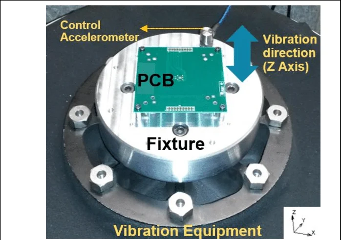
High-speed interfaces dominate infotainment PCBs, requiring precise length matching for USB 3.0, HDMI, and DisplayPort signals to prevent skew. Differential pairs must maintain 100-ohm impedance across multilayers, often 8 to 16 layers thick. EMI suppression demands ground planes and via fencing, while thermal hotspots from GPUs necessitate copper pours and vias. Vibration resistance calls for secure component mounting and anchor points per automotive guidelines. Power delivery networks (PDNs) handle surges from amplifiers, needing decoupling strategies. Software must verify these through pre-layout simulations and post-route analysis.
Signal integrity issues arise from reflections in unterminated traces or crosstalk between adjacent nets. Automotive environments exacerbate noise with engine harmonics coupling into sensitive audio paths. Stackup planning controls return paths and reduces loop inductance. Engineers apply via-in-pad for HDI transitions in compact modules. Compliance with ISO 26262 functional safety influences partitioning for fault isolation. Robust DRC engines flag violations like minimum annular ring or solder mask expansion.
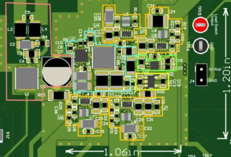
Layer management grows complex with power, ground, and signal planes interleaved for low inductance. Material selection favors low-loss dielectrics like FR-408 for gigabit speeds. Software visualization aids in identifying blind vias or microvias feasibility. Fabrication yields improve with teardrop generation on pads. Testing provisions include fiducials and test points for in-circuit validation. Mastering these principles separates viable designs from prototypes.
Comparing PCB Design Software Features for Automotive Infotainment
Altium Designer automotive PCB workflows shine in unified environments combining schematic, layout, and simulation. Its active routing handles interactive push-and-shove for dense boards, ideal for infotainment's fine-pitch BGAs and QFNs. Built-in signal integrity tools analyze reflections and crosstalk pre-layout, supporting S-parameters for automotive frequencies up to 10 GHz. Hierarchical design sheets manage large schematics for multi-board systems. 3D STEP export integrates with MCAD for enclosure fitment. DRC customizable to IPC standards flags automotive-specific rules like 0.15 mm min trace width.
Eagle PCB infotainment designs leverage Fusion 360 linkage for mechanical co-design, useful for dashboard enclosures. ULP scripts extend functionality for custom autorouters, though manual intervention prevails for high-speed. Multilayer support reaches 16 layers, sufficient for most infotainment but with board size limits in base versions. Libraries include automotive footprints, but users often curate for AEC-Q components. DRC enforces basic spacing, yet lacks native PI simulation. Ease of use suits mid-complexity projects transitioning from prototypes.
KiCad PCB design review reveals strong open-source growth with version 8+ enhancements in push-and-shove routing and differential pairs. Free access appeals to teams prototyping infotainment modules, supporting unlimited layers and board sizes. Interactive router aids length tuning, though less polished than commercial peers. 3D viewer improved for ray-tracing renders, aiding thermal airflow checks. DRC via Electrical Rules Checker (ERC/DRC) aligns with IPC-A-600 criteria, but advanced SI requires external plugins. Community-driven symbol libraries expand for connectors like FAKRA.
Feature Comparison
- Unified Environment: Altium - full integration; Eagle - schematic + layout + MCAD link; KiCad - separate but integrated project manager.
- High-Speed Routing: Altium - advanced diff pairs, length matching, SI analysis; Eagle - basic diff pairs with manual tuning; KiCad - improved interactive with plugin support.
- Multilayer Support: Altium - unlimited including HDI; Eagle - up to 16; KiCad - unlimited.
- DRC Customization: Altium - extensive, IPC-compliant; Eagle - standard plus ULP; KiCad - ERC/DRC with customizable nets.
- 3D Integration: Altium - native STEP and MCAD; Eagle - via Fusion 360; KiCad - built-in viewer and STEP export.
- Simulation: Altium - native PDN and SI/PI; Eagle - external; KiCad - external (ngspice and plugins).
- Cost: Altium - subscription, high; Eagle - free tier plus paid; KiCad - free/open-source.
This highlights trade-offs: Altium for enterprise-scale infotainment, Eagle for collaborative mid-tier, KiCad for cost-sensitive reviews.
Best Practices for Selecting and Using PCB Design Software Automotive
Start with project scale: Altium Designer automotive PCB excels for 10+ layer boards with gigabit Ethernet. Define rules early, setting clearance to 0.127 mm and via diameter per J-STD-001 for soldered joints. Verify stackups with field solver for 50/100-ohm control. For Eagle PCB infotainment, leverage design links for variant management across trims. KiCad PCB design review benefits from bus aliasing in schematics for repetitive CAN nodes. All tools support ODB++ output for fab houses.
Implement design variants for regional features like FM vs DAB tuners. Use polygon pours for PDN with stitched vias every 1/20 wavelength. Post-route, run hyperlynx-like analysis if available. Collaborate via version control; Altium's Concord Pro fits teams. Prototype small runs to validate before full infotainment spin. Train on software-specific shortcuts for productivity.
Thermal simulation integration prevents hotspots; embed thermals in layout phase. Automotive certification demands traceability, so annotate revisions per ISO 9001. Panelize for volume with breakaways. These practices maximize the best PCB design software automotive potential.
Troubleshooting Common Issues in Infotainment PCB Design
Crosstalk in video lines manifests as ghosting; mitigate with guard traces and ground stitching. Altium's analyzer quantifies NEXT/FEXT early. Power droop during audio peaks requires wide planes; Eagle's ratsnest helps visualize. KiCad users script for decap optimization. EMI failures trace to unshielded edges; add fences and chamfers. Vibration cracks at vias demand larger pads.
Board warpage from asymmetric stackups warps connectors; balance copper pour. Review bow and twist under IPC-A-600. Signal skew beyond 50 ps/bit errors HDMI; tune serpentine in all tools. Component obsolescence hits automotive quals; maintain parametric searches. Iterative DFM checks catch these pre-tapeout.
Conclusion
Choosing PCB design software for automotive infotainment hinges on complexity, budget, and team expertise. Altium Designer automotive PCB leads in advanced analysis for mission-critical layouts. Eagle PCB infotainment offers accessible integration for evolving designs. KiCad PCB design review provides viable free options with growing capabilities. Prioritize tools with robust DRC, high-speed support, and 3D features to meet IPC and ISO demands. Electrical engineers benefit most from hands-on evaluation matching project needs.
FAQs
Q1: What makes Altium Designer the best PCB design software automotive for infotainment?
A1: Altium Designer excels with native signal integrity tools, unlimited multilayer support, and customizable DRC for IPC-6012DS compliance. Its unified interface streamlines schematic-to-PCB flows for high-speed Ethernet and video. Engineers appreciate PDN analyzer for stable power in mixed-signal boards. This reduces iterations in dense layouts. Overall, it suits professional automotive workflows efficiently.
Q2: How does Eagle PCB infotainment handle high-speed designs?
A2: Eagle supports differential pairs and length matching via interactive routing, integrated with Fusion for 3D checks. It manages up to 16 layers suitable for many infotainment units. Custom ULPs extend DRC for EMI rules. Limitations include no built-in SI simulation, relying on exports. Ideal for mid-scale projects balancing cost and features.
Q3: Is KiCad PCB design review sufficient for automotive prototypes?
A3: KiCad offers free multilayer routing and ERC/DRC aligning with IPC Class 3 basics. Version 8+ improves push-and-shove for diff pairs in infotainment schematics. Community libraries aid component placement. External tools supplement SI analysis. It works well for reviews and proofs-of-concept before scaling.
Q4: What standards should PCB design software automotive enforce?
A4: Software must support DRC for IPC-6012DS automotive quals, J-STD-001 soldering, and ISO 26262 safety partitioning. Key rules cover trace spacing, via reliability, and thermal vias. This ensures high-reliability infotainment PCBs withstand vehicle stresses.
References
IPC-6012DS - Qualification and Performance Specification for Rigid Printed Boards Automotive Addendum. IPC
IPC-A-600K - Acceptability of Printed Boards. IPC, 2020
J-STD-001H - Requirements for Soldered Electrical and Electronic Assemblies. IPC/JEDEC
ISO 26262:2018 - Road vehicles - Functional safety. ISO