Introduction
Robotics control printed circuit boards handle diverse power demands, from low-voltage microcontrollers processing sensor data to high-current motor drivers enabling precise movements. Effective robotics PCB power distribution ensures stable voltage delivery across these varying loads, minimizing voltage droop and noise that could compromise control accuracy. Power integrity becomes critical in such systems, where transient currents from actuators can spike suddenly, demanding low-impedance paths to maintain performance. Voltage regulation through efficient DC-DC converters and robust battery management further enhances system reliability, especially in battery-powered mobile robots operating in dynamic environments. Power plane design plays a pivotal role, providing low-inductance distribution while mitigating electromagnetic interference. This article explores these elements, offering engineering-focused guidance for designing PDNs that prioritize efficiency and long-term reliability in robotics applications.
Understanding Power Distribution Networks in Robotics PCBs
A power distribution network in robotics PCBs encompasses the entire pathway from the power source, such as a battery pack, to individual components like processors, sensors, and drivers. It includes traces, planes, regulators, and decoupling elements that collectively manage current flow and voltage stability. In robotics, PDNs must support mixed-signal environments where digital switching noise could interfere with analog precision, making isolation and filtering essential. Why does this matter? Poor PDN design leads to inefficiencies, such as excessive heat generation that shortens battery life, or reliability issues like intermittent failures during high-load maneuvers. Engineers must consider dynamic load profiles, where motor startups draw peak currents far exceeding steady-state values, to prevent system resets or erratic behavior. Adhering to established guidelines ensures the PDN meets the stringent demands of real-time control in autonomous or teleoperated robots.
Core Principles of Power Integrity
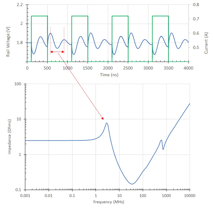
Power integrity focuses on maintaining clean, stable power delivery by controlling the PDN's impedance profile across frequencies from DC to GHz ranges. The target impedance concept guides design, where the PDN impedance must remain below a threshold calculated as Vdd / (I_max * ripple_tolerance) to limit voltage fluctuations. In robotics PCBs, high-speed digital circuits generate simultaneous switching noise, amplifying the need for distributed capacitance to absorb transients. Decoupling capacitors, placed strategically near loads, form a parallel LC network with the PDN inductance, smoothing ripples effectively. Simulations help predict resonance peaks, allowing adjustments before fabrication. Robust power integrity directly supports voltage regulation, ensuring control signals remain accurate even under varying thermal and mechanical stresses.
Voltage Regulation Strategies: DC-DC Converters and Beyond
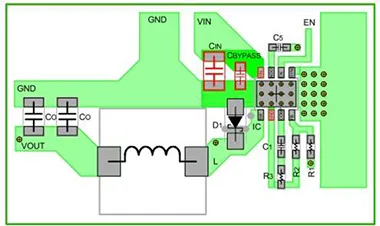
Voltage regulation in robotics control PCBs often relies on DC-DC converters for their high efficiency in stepping down battery voltages to multiple rails like 3.3V for logic and 5V or 12V for peripherals. These switch-mode regulators minimize power loss compared to linear alternatives, crucial for extending operational time in untethered robots. However, their switching action introduces high-frequency noise, necessitating careful PCB layout to contain electromagnetic fields. Low-dropout regulators complement DC-DC stages for noise-sensitive analog sections, providing final polishing of supply rails. Battery management integrates protection circuits for overcharge, over-discharge, and cell balancing, interfacing seamlessly with the PDN to monitor state-of-charge accurately. Selecting converter topologies like buck or buck-boost depends on input voltage range and load requirements, always prioritizing thermal margins in compact robotics enclosures.
Power Plane Design Fundamentals
Power plane design forms the backbone of robotics PCB power distribution, offering vastly lower impedance than trace-based routing for high currents. Solid copper pours on inner layers distribute power uniformly, reducing voltage gradients across the board. Careful splitting of planes prevents current loops that induce noise, with stitching vias bridging gaps to maintain continuity. Proximity to ground planes enhances decoupling through distributed capacitance, typically on the order of picofarads per square centimeter depending on dielectric thickness. In multilayer boards common to robotics, alternating power and ground planes in the stackup minimizes loop inductance. According to IPC-2221, conductor sizing and plane thickness must account for thermal rise, ensuring reliability under sustained loads.
Engineers should avoid routing signals over plane splits to prevent return path disruptions, which exacerbate EMI. For robotics applications with high-power motors, thicker copper weights like 2 oz/ft2 on power layers support elevated current densities without excessive heating.
Best Practices for Efficient and Reliable PDNs
Start with a symmetric layer stackup, placing power planes adjacent to ground for tight coupling and low inductance. Use via-in-pad or blind vias for high-density connections, minimizing parasitic inductance in current paths. Place bulk and ceramic decoupling capacitors as close as possible to IC power pins, following a hierarchical approach from high to low capacitance values. For DC-DC converters, shorten high-current loops and route gate drive signals over ground planes to shield switching noise. Implement battery management with dedicated sense lines isolated from main power paths, incorporating fuses or eFuses for fault protection.
Thermal management integrates with PDN design; wider traces or embedded heat spreaders dissipate heat from regulators. Power integrity verification through time-domain reflectometry or impedance profiling confirms design margins pre-prototype. These practices, aligned with IPC-2152 for current-carrying capacity, yield PDNs that excel in robotics' demanding conditions.
Integrating Battery Management Systems
Battery management in robotics PCBs optimizes power extraction while safeguarding lithium-ion or similar packs against abuse. The system monitors individual cell voltages, temperatures, and currents, feeding data to the controller for dynamic load shedding. Integration into the PDN requires low-resistance shunts for accurate coulomb counting and isolated communication interfaces to avoid ground shifts. Efficient DC-DC front-ends from battery voltage handle wide input swings during discharge. Protection circuitry, including MOSFET-based switches, disconnects loads during faults without interrupting control logic. This holistic approach ensures the PDN supports extended missions with minimal downtime.
Common Challenges and Troubleshooting Insights
Dynamic loads in robotics often cause PDN resonance, manifesting as jitter in control loops; adding ferrite beads or targeted damping resistors resolves this. Voltage droop under motor inrush can be mitigated by pre-charging capacitors or soft-start features in converters. EMI from power planes coupling to antennas requires shielding cans or guard traces. Troubleshooting starts with scoping power rails during worst-case transients, correlating issues to layout flaws. Iterative simulation refines designs, preventing field failures in safety-critical robots.
Conclusion
Designing power distribution networks for robotics control PCBs demands a balanced approach to power integrity, voltage regulation, and power plane optimization. By prioritizing low-impedance paths, efficient DC-DC converters, and robust battery management, engineers achieve systems that deliver reliable performance under real-world stresses. Adhering to proven best practices minimizes risks like noise injection and thermal overload, extending battery life and operational uptime. As robotics evolves toward greater autonomy, PDN excellence remains foundational to precision and safety. Implementing these strategies positions designs for success in competitive applications.
FAQs
Q1: What is robotics PCB power distribution, and why is it critical?
A1: Robotics PCB power distribution refers to the network delivering stable power from sources like batteries to diverse loads such as motors and sensors. It ensures efficiency by minimizing losses and supports reliability through low-impedance paths that prevent voltage sags. In dynamic environments, poor distribution leads to control errors or failures, making it essential for mission-critical performance. Following structured design principles addresses these challenges effectively.
Q2: How does power integrity impact voltage regulation in robotics PCBs?
A2: Power integrity maintains PDN impedance below targets, enabling precise voltage regulation via DC-DC converters. It suppresses noise from switching, preserving rail stability for sensitive analog circuits. In robotics, this prevents jitter in feedback loops, enhancing overall system accuracy. Engineers verify integrity through simulations to meet operational demands.
Q3: What role does power plane design play in robotics applications?
A3: Power plane design provides low-inductance distribution for high currents in motor drivers while isolating noise domains. Solid planes with stitching vias ensure uniform voltage, critical for battery-powered robots. Proper stackup adjacency to ground planes boosts capacitance, aiding transient response. This foundation supports scalable, reliable PDNs.
Q4: Why integrate battery management with PCB power distribution?
A4: Battery management monitors and protects packs, interfacing with the PDN to optimize power delivery and prevent overstress. It enables efficient DC-DC regulation across discharge cycles, extending runtime in mobile robotics. Isolated monitoring avoids PDN contamination, ensuring long-term reliability without compromising control integrity.
References
IPC-2221B — Generic Standard on Printed Board Design. IPC, 2003
IPC-2152A — Standard for Determining Current Carrying Capacity in Printed Board Design. IPC, 2009
J-STD-001H — Requirements for Soldered Electrical and Electronic Assemblies. IPC, 2018