What is solder joint fatigue and why is it crucial for electronics?
Solder joints serve as the indispensable electrical and mechanical connections within electronic assemblies, linking components to printed circuit boards (PCBs). However, these critical interconnections are highly susceptible to fatigue, a degradation process involving the initiation and propagation of cracks under repeated stress, ultimately leading to failure. This fatigue is primarily driven by environmental factors such as recurrent temperature fluctuations (thermal cycling fatigue) and continuous mechanical vibrations (vibration fatigue).
For electrical engineers, comprehending and accurately predicting solder joint fatigue is paramount. Failures in these joints can instigate severe consequences, including costly system downtime, expensive repairs, and potential safety hazards, particularly in high-reliability applications found in sectors like aerospace and automotive industries. Therefore, mastering the prediction of solder joint lifespan is fundamental to designing robust and dependable electronic products.

Understanding the main stressors on solder joints
The integrity of solder joints is predominantly challenged by two types of repetitive stress: thermal cycling and mechanical vibration. Thermal cycling fatigue in solder arises from the disparate rates at which different materials within a PCB assembly expand and contract with temperature changes. As a device heats up during operation and cools down when idle, these material mismatches induce cyclical stresses within the solder, eventually causing micro-cracks to form and propagate.
Simultaneously, vibration fatigue in solder joints is a consequence of mechanical forces, such as those experienced in moving vehicles or industrial machinery. Constant or intermittent vibrations impose cyclical mechanical loads on the joints, leading to cumulative damage and weakening of the solder bond over time. Often, both thermal and vibration stresses can act concurrently, accelerating the degradation process and shortening the operational life of the solder joints.
How can engineers predict solder joint fatigue life?
Accurately predicting how long a solder joint will last under operational conditions is a complex but essential task for ensuring product reliability. Engineers employ a combination of sophisticated simulation techniques and empirical models to estimate the fatigue life of these critical connections.
Finite Element Analysis (FEA) for solder fatigue
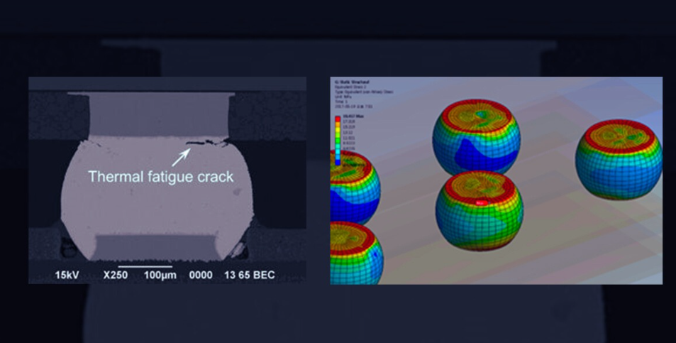
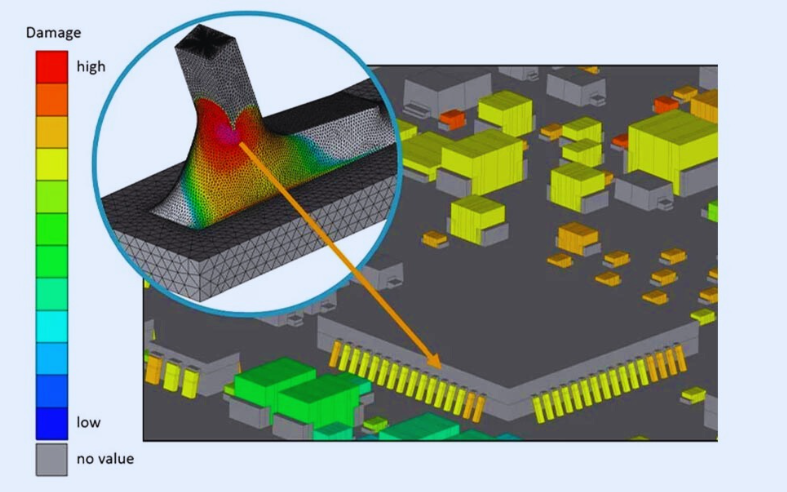
Finite Element Analysis (FEA) stands as a powerful simulation method used to model the mechanical behavior of solder joints under various stress conditions. Utilizing specialized PCB design and analysis software, such as ANSYS or Abaqus, engineers construct detailed digital representations of solder joints. They then apply simulated thermal loads, reflecting temperature cycles, or mechanical loads, mimicking vibrations, to these models. FEA excels at predicting stress distribution, strain accumulation, and pinpointing potential areas of failure within the joint with high precision.
For example, an FEA simulation of a ball grid array (BGA) package undergoing thermal cycling between -40°C and 125°C might reveal peak stress concentrations of 50 MPa at specific corners of the solder balls. By analyzing these results, engineers can use established fatigue models, like the Coffin-Manson equation, to estimate the number of cycles until failure. This allows for virtual testing of designs before committing to proto PCB boards, significantly saving time and reducing manufacturing costs. However, successful FEA requires expert knowledge of material properties, including the solder's creep behavior and elastic modulus (e.g., 40 GPa for SAC305 solder alloy), to ensure accurate input data.
Using empirical models and accelerated life testing (ALT)
Beyond FEA, empirical models provide another valuable approach to solder joint fatigue life prediction. Models such as the Engelmaier model leverage extensive experimental data to correlate specific stress conditions with expected fatigue life. For instance, the Engelmaier model can predict the number of cycles to failure by analyzing the shear strain experienced by solder joints during thermal cycling, taking into account temperature ranges and dwell times.
Complementing these models, Accelerated Life Testing (ALT) involves subjecting solder joints to exaggerated environmental stresses (e.g., rapid temperature changes from -55°C to 125°C every 30 minutes) to drastically shorten the time to failure. The failure data gathered from ALT is then extrapolated to normal operating conditions using models like the Arrhenius equation, which adjusts for temperature-dependent degradation rates. ALT can compress months of real-world degradation into weeks of testing, making it a highly practical tool in the product development cycle.
Practical methods for solder joint fatigue testing
While advanced simulations provide critical insights, physical testing remains an indispensable step to validate predictions and ensure the real-world robustness of solder joints. Solder joint fatigue testing involves subjecting electronic assemblies to controlled stress conditions and meticulously monitoring them for signs of failure.
Thermal cycling and vibration test protocols
Thermal cycling tests are designed to precisely replicate the temperature fluctuations experienced by electronic devices in their operational environment. These tests typically involve cycling the temperature within a specialized chamber between predefined extremes (e.g., -40°C to 125°C) for a specified number of cycles. Throughout the test, the solder joints are continuously monitored for electrical continuity or subtle signs of physical degradation, such as micro-cracks, often detected using advanced microscopy or X-ray imaging. Industry standards, like IPC-9701, provide specific test profiles and benchmarks, with 1,000 cycles frequently cited as a baseline for demonstrating reliability.
For assessing vibration fatigue in solder joints, vibration testing employs shaker tables that subject assemblies to mechanical stress mimicking real-world conditions. These tests adhere to standards such as MIL-STD-810, which define specific frequency ranges (e.g., 20-2,000 Hz for automotive components) and amplitudes relevant to the product's application. Failure during vibration testing is typically identified through continuous electrical checks, where an interruption in conductivity signals the formation of cracks within the solder joint. Both thermal and vibration testing provide invaluable empirical data that refines FEA models and empirical predictions, ultimately ensuring the design's resilience.
Strategies to prevent solder joint fatigue failures
Proactively preventing solder joint failures is just as crucial as predicting them. Implementing strategic approaches in material selection, design optimization, and manufacturing quality can significantly enhance the long-term reliability of electronic products.
Optimizing materials, design, and manufacturing
The choice of solder alloy is foundational. While lead-free solders, such as SAC305 (Sn-3.0Ag-0.5Cu), are prevalent due to environmental regulations, they often exhibit lower fatigue resistance than traditional lead-based solders. For demanding applications, engineers might consider lead-free alloys with specific additives like bismuth or indium, known for improving fatigue performance.
Design optimization plays a pivotal role. Minimizing mismatches in the coefficient of thermal expansion (CTE) between components and the PCB (e.g., using FR-4 boards with a CTE of 14-17 ppm/°C for common IC packages) can drastically reduce thermal stress on solder joints. Furthermore, strategic component placement, avoiding large components near board edges where vibration stress is often concentrated, is beneficial. Incorporating underfill materials, particularly for BGA packages, can distribute stress more evenly and extend joint lifespan by up to 50%.
Manufacturing quality is equally critical. Flaws introduced during soldering, such as voids or inadequate wetting, can act as stress concentrators, accelerating fatigue. Techniques like vacuum reflow soldering can minimize voiding (aiming for less than 10% void area per joint), while meticulous flux application ensures robust metallurgical bonds. Post-assembly inspection using X-ray or acoustic microscopy can detect these subtle defects early, preventing them from becoming latent failure points.
Real-world applications and future trends in fatigue analysis
The principles of solder joint fatigue analysis are applied across various industries where electronic reliability is paramount. Continuous advancements are also shaping the future of prediction and prevention.
Industry applications and emerging technologies
In the automotive sector, where electronic control units (ECUs) are exposed to constant thermal cycling and vibration, these fatigue analysis principles are critically important. For instance, a major automotive manufacturer discovered that combining SAC305 solder with an underfill material could increase solder joint fatigue life by 40% under combined thermal (-40°C to 105°C) and vibration (50 Hz) test conditions, leading to substantial reductions in warranty claims. Similarly, in the aerospace industry, where mission-critical systems demand absolute reliability, engineers heavily rely on Finite Element Analysis for solder fatigue to simulate extreme conditions, such as rapid temperature changes experienced during flight (e.g., 25°C to -55°C within minutes). This FEA is often coupled with rigorous solder joint fatigue testing to ensure systems perform flawlessly in operation.
Despite significant progress, challenges persist. The trend towards miniaturization in electronics results in smaller solder joints with less material to absorb stress, potentially reducing fatigue life. Furthermore, the introduction of novel materials, such as high-temperature solders for advanced 5G applications, necessitates the development of updated fatigue models due to limited existing data. Looking ahead, machine learning is emerging as a transformative tool for solder joint fatigue life prediction. By training algorithms on extensive datasets derived from FEA simulations and physical testing, engineers are poised to predict failures with unprecedented accuracy, with industry reports suggesting that AI-driven models could reduce prediction errors by 20% within the next five years.
Enhancing solder joint reliability for robust designs
Effectively managing solder joint fatigue is a complex, yet entirely surmountable, challenge for electrical engineers. By integrating advanced analytical tools and strategic preventative measures, designers can significantly extend the lifespan and reliability of their electronic products. The core approach involves a combination of leveraging Finite Element Analysis (FEA) for solder fatigue, conducting thorough physical solder joint fatigue testing, and meticulously optimizing both material selection and design layouts.
Engineers should actively incorporate these practices into their daily workflow, from initiating early FEA simulations to refining thermal cycling test protocols. By proactively addressing issues like thermal cycling fatigue in solder and vibration fatigue in solder joints, designs will not only become more robust but also achieve greater overall dependability, ultimately leading to more successful and enduring electronic products.