Introduction
In the realm of high-speed electronic design, ensuring reliable signal transmission is paramount for electrical engineers. Signal integrity, a critical factor in modern printed circuit board (PCB) layouts, hinges on understanding transmission line theory. This concept governs how signals propagate through conductive traces, impacting performance through phenomena like signal reflection and signal attenuation. Mastery of characteristic impedance and proper termination techniques can prevent data corruption and timing errors in high-frequency applications. As systems operate at ever-increasing speeds, impedance control becomes essential to maintain signal quality. This article explores the fundamentals of transmission line theory, delving into its technical principles and offering practical solutions for engineers. Whether designing for telecommunications or computing, these insights aim to enhance circuit reliability and efficiency.
What Is Transmission Line Theory and Why It Matters
Transmission line theory is a framework used to analyze the behavior of electrical signals as they travel along conductive paths, such as PCB traces or cables. Unlike simple lumped circuit models, this theory accounts for distributed inductance and capacitance along the conductor, which become significant at high frequencies. When signal wavelengths approach the physical dimensions of the transmission medium, wave propagation effects emerge, necessitating a detailed understanding.
This theory matters because it directly influences signal integrity in modern electronics. As data rates climb into the gigahertz range, even small mismatches in characteristic impedance can lead to reflections, causing signal distortion or loss. Poor impedance control results in crosstalk, electromagnetic interference, and timing issues, all of which degrade system performance. For electrical engineers, applying transmission line theory ensures that signals reach their destination with minimal degradation, preserving data accuracy in critical applications like servers, communication devices, and automotive systems.
Technical Principles of Transmission Line Theory
Characteristic Impedance and Its Role
Characteristic impedance is a fundamental property of a transmission line, defined as the ratio of voltage to current for a traveling wave. It depends on the line's geometry, material properties, and surrounding dielectric. A uniform transmission line with consistent impedance allows signals to propagate without reflection. However, mismatches between the source, line, and load impedance disrupt this balance, leading to signal reflection.
The importance of characteristic impedance lies in its ability to predict how a signal will behave along the line. If the load impedance equals the characteristic impedance, the signal is fully absorbed. If not, a portion of the signal reflects back toward the source, causing interference. Standards like IPC-2141A provide guidelines for designing controlled impedance traces on types of PCBs to minimize such issues.
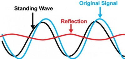
Signal Reflection and Its Causes
Signal reflection occurs when a traveling wave encounters a discontinuity in impedance along the transmission path. This discontinuity can arise from an unmatched load, a change in trace width, or a connector. The reflected wave interferes with the incident wave, potentially causing voltage overshoots or undershoots that distort the signal.
Reflections are quantified by the reflection coefficient, which depends on the difference between the load and characteristic impedance. A larger mismatch results in a higher reflection coefficient, increasing the reflected energy. Engineers must address this to prevent data errors, especially in high-speed digital circuits where timing is critical.
Signal Attenuation in Transmission Lines
Signal attenuation refers to the loss of signal strength as it propagates along a transmission line. This loss stems from conductor resistance, dielectric losses, and radiation effects. At high frequencies, skin effect and dielectric absorption further contribute to attenuation, reducing the amplitude of the signal.
Attenuation impacts long transmission lines more severely, as losses accumulate over distance. For electrical engineers, understanding attenuation is vital when designing systems that transmit signals over extended traces or cables. Mitigating these losses often involves selecting appropriate materials and optimizing trace geometries, as outlined in standards like IPC-6012E for PCB performance.
Termination Techniques to Minimize Reflections
Termination is a strategy used to match the load impedance to the characteristic impedance of the transmission line, thereby minimizing reflections. Common termination methods include series termination, where a resistor is placed near the source, and parallel termination, where a resistor connects to ground at the load end.
Proper termination absorbs the signal energy at the load, preventing reflections from traveling back. Without it, reflected signals can cause ringing or double-switching in digital circuits. Engineers must carefully select termination values based on the line's characteristic impedance to ensure optimal performance.
Practical Solutions for Impedance Control and Signal Integrity
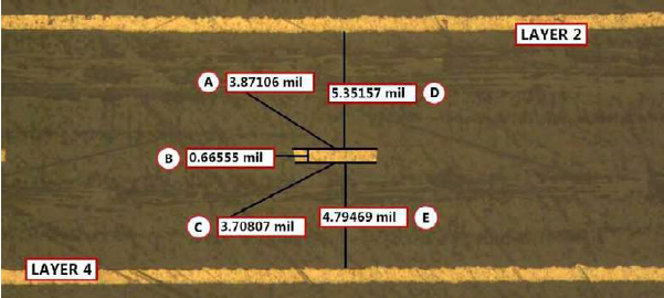
Designing for Controlled Impedance
Achieving controlled impedance starts with precise PCB design. Engineers must define trace widths, spacing, and layer stackups to match the desired characteristic impedance. Reference planes, typically ground or power layers, play a crucial role in maintaining consistent impedance by providing a return path for signals.
Standards such as IPC-2141A offer detailed methodologies for calculating trace dimensions based on dielectric properties and frequency requirements. Using simulation tools to model impedance before fabrication can also identify potential issues. Additionally, maintaining uniform trace routing without abrupt changes in width or direction helps avoid impedance discontinuities.
Suggested Reading: How to calculate impedance of transmission lines for high speed PCB designs
Material Selection for Reduced Attenuation
Material properties significantly affect signal attenuation in transmission lines. High-frequency signals require low-loss dielectrics with stable dielectric constants to minimize energy absorption. Conductor materials with low resistivity reduce ohmic losses, especially at high frequencies where skin effect dominates.
When selecting PCB materials, engineers should consult specifications that align with industry standards like IPC-4101E for laminate performance. Balancing cost and performance is key, as advanced materials often come with higher expenses but offer superior signal integrity for demanding applications.
Implementing Effective Termination Strategies
To implement termination, engineers must first determine the characteristic impedance of the transmission line, often through simulation or measurement. Series termination is effective for point-to-point connections, placing a resistor close to the driver to match impedance. Parallel termination, often used in multi-drop configurations, requires careful placement to avoid excessive power consumption.
Testing different termination schemes during the design phase helps identify the most effective approach. Adhering to guidelines in standards like IPC-6012E ensures that termination components meet reliability and performance criteria under operating conditions.
Testing and Validation for Signal Integrity
Validating signal integrity involves measuring key parameters like reflection coefficient and attenuation using tools such as time-domain reflectometry (TDR) or vector network analyzers (VNA). TDR helps locate impedance discontinuities along the line, while VNA provides frequency-domain insights into signal loss.
Engineers should establish test criteria based on standards like IPC-A-600K for PCB acceptability, ensuring that fabricated boards meet design specifications. Regular validation during prototyping and production phases catches issues early, preventing costly redesigns.
Troubleshooting Common Signal Integrity Issues
In practice, signal integrity problems often manifest as data errors, timing violations, or unexpected noise. A common issue is excessive signal reflection due to improper termination or mismatched impedance. Engineers can resolve this by recalculating trace impedance and adjusting termination resistors accordingly.
Another frequent challenge is signal attenuation in long traces, which can be mitigated by shortening trace lengths or using repeaters to boost signal strength. Crosstalk, caused by electromagnetic coupling between adjacent traces, requires increased spacing or the addition of ground planes for shielding. Methodical troubleshooting, guided by standards such as IPC-A-600K, ensures that root causes are identified and addressed systematically.
Conclusion
Signal integrity and impedance control are cornerstones of high-speed electronic design, deeply rooted in transmission line theory. By grasping concepts like characteristic impedance, signal reflection, and signal attenuation, electrical engineers can design systems that deliver reliable performance. Practical strategies, including controlled impedance design, material selection, and termination, provide actionable ways to enhance signal quality. Regular testing and adherence to industry standards ensure that designs meet stringent requirements. As technology pushes frequency limits higher, mastering these principles remains essential for creating robust and efficient circuits.
FAQs
Q1: What is transmission line theory and how does it relate to PCB design?
A1: Transmission line theory explains how electrical signals propagate along conductive paths like PCB traces. It accounts for distributed inductance and capacitance, which affect high-frequency signals. In PCB design, this theory guides impedance control to prevent issues like signal reflection, ensuring reliable data transmission. Understanding these principles helps engineers create layouts that maintain signal integrity across various applications.
Q2: How does signal reflection impact high-speed circuits?
A2: Signal reflection occurs when impedance mismatches cause part of a signal to bounce back toward the source. In high-speed circuits, this can lead to voltage overshoots, ringing, or data errors. Reflections disrupt timing and degrade signal quality, making impedance matching and proper termination critical for maintaining performance in fast-switching digital systems.
Q3: What are the best practices for controlling characteristic impedance on PCBs?
A3: Controlling characteristic impedance involves precise trace design, including width, thickness, and spacing, alongside consistent dielectric properties. Using reference planes for return paths and following guidelines in standards like IPC-2141A ensures accuracy. Simulation during design and validation post-fabrication help confirm that the impedance matches the intended value for optimal signal transmission.
Q4: How can signal attenuation be minimized in long PCB traces?
A4: Signal attenuation in long PCB traces can be reduced by selecting low-loss dielectric materials and high-conductivity conductors. Shortening trace lengths or using signal repeaters also helps. Adhering to material specifications in standards like IPC-4101E ensures minimal energy loss, preserving signal strength over distance in high-frequency applications.
References
IPC-2141A — Design Guide for High-Speed Controlled Impedance Circuit Boards. IPC, 2004.
IPC-6012E — Qualification and Performance Specification for Rigid Printed Boards. IPC, 2020.
IPC-A-600K — Acceptability of Printed Boards. IPC, 2020.
IPC-4101E — Specification for Base Materials for Rigid and Multilayer Printed Boards. IPC, 2017.


