Introduction
Welcome to a detailed guide on reflowing Surface Mount Technology (SMT) components onto Aluminum Printed Circuit Boards (PCBs). For electronic hobbyists, mastering SMT assembly opens doors to creating compact, high-performance circuits. Aluminum PCBs, known for excellent thermal conductivity, are often used in applications like LED lighting and power electronics. This article, crafted with practical insights, walks beginners through the reflow process step by step. From understanding the unique properties of aluminum substrates to executing a successful reflow, you will gain the knowledge needed to tackle this task with confidence. Whether you are assembling a prototype or exploring new materials, this guide focuses on essential techniques and best practices for working with SMT components and aluminum PCBs.
What Are SMT Components and Aluminum PCBs?
SMT components are electronic parts designed to be mounted directly onto the surface of a PCB, eliminating the need for through-hole drilling. These components, such as resistors, capacitors, and integrated circuits, enable smaller, lighter designs ideal for modern electronics. Their small size and high density make them a staple in consumer gadgets and industrial devices.
Aluminum PCBs differ from standard FR4 boards due to their metal core, which provides superior heat dissipation. Typically, they consist of a thin dielectric layer sandwiched between a copper circuit layer and an aluminum base. This structure makes them perfect for applications where thermal management is critical. For hobbyists, working with aluminum PCBs means addressing unique challenges like thermal expansion differences during reflow soldering. Understanding these materials and components sets the foundation for a successful assembly process.
Related Reading: Aluminum PCBs: An Essential Solution for High-Performance Electronics
Why Reflowing SMT on Aluminum PCBs Matters
Reflow soldering is a widely used method to attach SMT components to PCBs by melting solder paste to form reliable electrical connections. When applied to aluminum PCBs, this process becomes crucial for ensuring performance in heat-intensive applications. The high thermal conductivity of aluminum helps dissipate heat from components, preventing overheating in devices like LED arrays or motor drivers. However, the material's rapid heat transfer also demands precise control during reflow to avoid uneven heating or component damage. For hobbyists, mastering this technique means creating durable, efficient circuits while navigating the unique thermal behavior of aluminum substrates. Proper reflow ensures strong solder joints and long-term reliability in your projects.
Technical Principles of Reflow Soldering on Aluminum PCBs
Reflow soldering involves applying solder paste to PCB pads, placing SMT components, and heating the assembly in a controlled manner to melt the solder. The process typically follows a temperature profile with distinct phases: preheat, soak, reflow, and cooling. Each phase plays a role in achieving consistent solder joints.
Aluminum PCBs introduce specific challenges due to their high thermal conductivity. Heat spreads quickly across the board, which can lead to uneven temperature distribution if not managed. This property requires adjustments in the reflow profile compared to standard FR4 boards. For instance, a slower preheat phase helps avoid thermal shock to components. Additionally, the coefficient of thermal expansion for aluminum differs from copper and components, potentially causing stress on solder joints if cooling is too rapid.
Standards like IPC J-STD-020E provide guidelines for moisture sensitivity and reflow profiles for SMT components. Following these ensures that components are not exposed to excessive heat or moisture, which could lead to failures like popcorn defects. For aluminum substrates, maintaining uniform heat distribution is vital to prevent warpage or delamination of the dielectric layer, as outlined in specifications like IPC-6012E for rigid board performance.
Step-by-Step Guide to Reflowing SMT Components on Aluminum PCBs
Step 1: Gather Tools and Materials
Before starting, ensure you have the necessary equipment. You will need a reflow oven or a hot plate with temperature control, solder paste compliant with industry standards, a stencil for precise paste application, tweezers for component placement, and a clean aluminum PCB. Safety gear like heat-resistant gloves and proper ventilation are also essential when working with soldering materials.
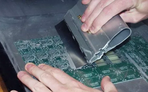
Step 2: Prepare the Aluminum PCB
Clean the PCB surface to remove any contaminants or oxidation that could affect solder adhesion. Use isopropyl alcohol and a lint-free cloth for this task. Inspect the board for flatness, as aluminum can warp under heat if not handled properly. Secure the PCB on a flat, heat-resistant surface to maintain stability during reflow.
Step 3: Apply Solder Paste
Using a stencil aligned with the PCB pads, apply solder paste evenly. The stencil ensures paste is deposited only on the contact areas for SMT components. Scrape the paste across the stencil with a squeegee at a consistent angle to avoid excess or insufficient application. Remove the stencil carefully to prevent smudging.
Step 4: Place SMT Components
With tweezers, place each SMT component onto the corresponding pads with solder paste. Ensure correct orientation, especially for polarized components like diodes or ICs. Precision here prevents issues like tombstoning, where components lift during reflow. Double-check placement against your design schematic before proceeding.
Step 5: Set Up the Reflow Process
If using a reflow oven, program it with a temperature profile suitable for aluminum PCBs. Refer to guidelines in IPC J-STD-020E for component-specific profiles, adjusting for the rapid heat transfer of aluminum. A typical profile might include a gradual preheat to minimize thermal shock, followed by a soak phase to equalize temperatures. For hobbyists using a hot plate, monitor temperatures manually with a thermometer to approximate these phases.
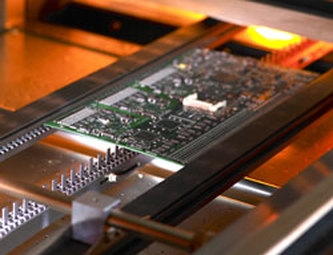
Step 6: Execute Reflow Soldering
Place the PCB in the reflow oven or on the preheated hot plate. Follow the temperature profile closely. During the reflow phase, solder paste melts to form joints between components and pads. Watch for uniform melting across the board, as aluminum's conductivity can cause hot spots. Avoid sudden temperature changes to prevent stress on the board or components.
Step 7: Cool Down and Inspect
After reflow, allow the PCB to cool gradually. Rapid cooling can induce thermal stress, especially with aluminum's expansion properties. Once cooled, inspect solder joints visually for consistency and shininess, indicating proper wetting. Use a magnifying glass to check for defects like bridging or insufficient solder. Standards like IPC-A-600K provide criteria for acceptable solder joint appearance.
Related Reading: The Reflow Soldering Process: A Practical Guide for Electrical Engineer’s Guide
Troubleshooting Common Issues with Aluminum PCBs
Hobbyists often face challenges when reflowing on aluminum PCBs. Uneven heating is a frequent issue due to the material's thermal properties. If components on one side reflow before others, adjust the oven setup or use a thermal mass like a metal plate under the PCB to balance heat distribution.
Warpage can occur if the board is not supported properly during heating. Ensure the PCB lies flat on a heat-resistant surface. If warpage persists, review the cooling rate, as rapid cooling exacerbates this problem. Refer to IPC-6012E for performance specifications related to board flatness.
Component misalignment or tombstoning often results from uneven paste application or incorrect placement. Revisit your stencil technique and confirm component orientation before reflow. These steps minimize defects and improve assembly outcomes.
Best Practices for Beginners
Start with small, simple projects to build confidence with SMT reflow on aluminum PCBs. Use a controlled environment to avoid variables like drafts affecting heat distribution. Always follow safety protocols when handling hot equipment or materials.
Document your reflow profile settings and outcomes for each project. This practice helps identify what works best for your setup. Additionally, store components and boards in moisture-controlled conditions to prevent issues during reflow, as advised by IPC J-STD-020E for moisture sensitivity.
Invest time in learning the thermal characteristics of aluminum compared to other substrates. This knowledge guides adjustments in your process. Finally, prioritize patience and precision over speed to ensure quality results in every assembly.
Conclusion
Reflowing SMT components on aluminum PCBs offers electronic hobbyists a pathway to creating efficient, thermally robust circuits. By understanding the unique properties of aluminum substrates and following a structured reflow process, beginners can achieve reliable solder joints. This guide has covered essential steps from preparation to inspection, alongside troubleshooting tips for common challenges. Adhering to industry standards ensures consistency and quality in your work. With practice, you can confidently tackle SMT assembly on aluminum PCBs, enhancing your skills and project outcomes in the exciting field of electronics.
FAQs
Q1: What are the main challenges when reflowing SMT components on aluminum PCBs?
A1: Reflowing SMT components on aluminum PCBs poses challenges like uneven heating due to high thermal conductivity. This can cause inconsistent solder melting. Warpage is another issue if the board isn't supported or cools too quickly. Beginners must adjust reflow profiles to manage heat distribution and prevent thermal stress, ensuring reliable joints as per industry guidelines.
Q2: How do aluminum PCBs differ from standard PCBs during SMT assembly?
A2: Aluminum PCBs have superior heat dissipation compared to standard FR4 boards, impacting SMT assembly. Their thermal conductivity requires modified reflow profiles to avoid hot spots or thermal shock to components. The differing expansion rates of aluminum and copper also demand careful cooling to prevent stress on solder joints during the process.
Q3: What tools are essential for beginners reflowing SMT components?
A3: Beginners need a reflow oven or hot plate with temperature control for reflowing SMT components. A stencil and squeegee ensure precise solder paste application. Tweezers aid in component placement, while a magnifying glass helps inspect joints. Safety gear like heat-resistant gloves and proper ventilation are crucial for handling heated materials safely.
Q4: Why is a controlled temperature profile important for aluminum PCBs?
A4: A controlled temperature profile is vital for aluminum PCBs to manage their rapid heat transfer. It prevents thermal shock to SMT components and ensures even solder melting. Gradual heating and cooling reduce stress and warpage risks, aligning with standards like IPC J-STD-020E to protect component integrity and achieve consistent assembly results.
References
IPC J-STD-020E - Moisture/Reflow Sensitivity Classification for Nonhermetic Surface Mount Devices. IPC, 2014.
IPC-6012E - Qualification and Performance Specification for Rigid Printed Boards. IPC, 2020.
IPC-A-600K - Acceptability of Printed Boards. IPC, 2020.


