Introduction
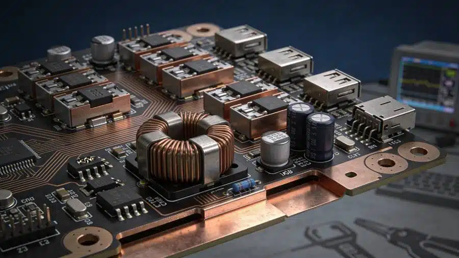
Power supplies form the backbone of most electronic systems, converting and regulating electrical energy to meet the demands of various components. In high-power applications, such as switching power supplies and DC-DC converters, excessive heat generation from components like MOSFETs, diodes, and transformers poses significant challenges to both efficiency and stability. Traditional FR4 PCBs struggle with thermal dissipation, leading to hotspots, reduced component lifespan, and performance degradation over time. Metal core PCBs address these issues by integrating a metal substrate that enhances thermal management, allowing power supplies to operate reliably under demanding conditions. This article explores the structure, principles, and design practices of metal core PCBs in power supplies, providing engineers with insights to optimize PCB design for superior efficiency and stability.
As power densities increase in modern electronics, effective thermal management becomes non-negotiable. Metal core PCBs enable tighter layouts and higher current handling without compromising reliability. Factory processes for these boards emphasize precise bonding of layers to ensure consistent heat transfer paths. Engineers benefit from their dimensional stability, which minimizes warpage during thermal cycling common in power supply operations.
What Are Metal Core PCBs and Why They Matter in Power Supplies
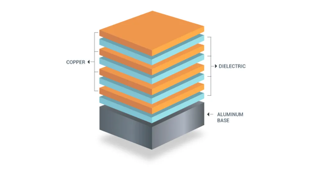
Metal core PCBs, also known as MCPCBs or insulated metal substrate boards, consist of three primary layers: a copper circuit layer, a thermally conductive dielectric layer, and a solid metal base, typically aluminum or copper. The copper layer carries traces and pads for components, while the thin dielectric isolates it electrically from the metal core but allows efficient heat conduction. This trilayer construction differs fundamentally from standard FR4 boards, where fiberglass reinforcement limits thermal conductivity to around 0.3 W/mK. In contrast, the metal core provides mechanical rigidity and a direct path for heat spreading, making MCPCBs ideal for applications exceeding 50W per square inch.
In power supplies, where efficiency directly correlates with minimal thermal losses, metal core PCBs play a pivotal role. Heat from rectifiers and inductors can cause voltage droop and ripple if not dissipated quickly, undermining stability. These boards transfer heat 8 to 9 times faster than FR4, maintaining junction temperatures within safe limits and boosting overall system efficiency by up to several percentage points through reduced throttling. Factory-driven insights reveal that aluminum cores, with their balance of cost and conductivity, dominate power supply designs, while copper suits ultra-high-power needs.
Dimensional stability is another key factor, as metal cores offer 2 to 4 times the rigidity of FR4, resisting warpage from solder reflow or operational stresses. This ensures consistent electrical performance in vibration-prone environments like industrial power supplies. For electric engineers, selecting metal core PCBs translates to longer mean time between failures (MTBF) and compliance with reliability expectations in continuous operation.
The Technical Principles of Thermal Management in Metal Core PCBs
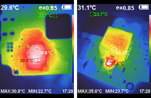
Thermal management in metal core PCBs relies on conduction as the primary mechanism, where heat from components flows through the copper pads, across the thin dielectric, and into the metal core for lateral spreading. The dielectric layer, typically 2 to 6 mils thick with conductivity of 1 to 3 W/mK, minimizes thermal resistance while providing electrical isolation greater than 3000V breakdown. Aluminum cores exhibit around 138 to 167 W/mK conductivity, far surpassing FR4, enabling uniform temperature distribution across the board. This principle prevents localized hotspots, crucial for stability in power supplies where temperature gradients can induce parasitic effects.
Efficiency gains stem from lower operating temperatures, which reduce conduction losses in semiconductors and improve power conversion rates. In switching power supplies, for instance, cooler MOSFETs maintain lower on-resistance, preserving output voltage stability under load variations. Factory processes ensure the metal core bonds uniformly to avoid delamination, a common failure mode under thermal cycling. Engineers must consider the coefficient of thermal expansion (CTE) mismatch, with aluminum at 25 μm/m-°C aligning reasonably with copper's 17 μm/m-°C via the dielectric.
Grounding the metal core enhances electromagnetic compatibility (EMC) by acting as a shield, while also serving as a heat sink interface. Unlike FR4 designs requiring extensive thermal vias, metal core PCBs simplify routing since heat spreads inherently through the base. IPC-2221 guidelines emphasize such thermal design considerations to balance electrical and mechanical performance in high-power layouts.
Best Practices in PCB Design for Power Supplies Using Metal Core PCBs
Effective PCB design for power supplies with metal core substrates begins with stackup planning, favoring symmetric configurations to prevent warpage. For multilayer boards, position the metal core centrally with equal dielectric and copper layers on both sides, such as six layers top and bottom in a 12-layer stack. Prefer surface-mount technology (SMT) components to avoid plated through-hole (PTH) shorts to the core; if PTHs are necessary, oversize core drills by 40 to 50 mils and fill with non-conductive epoxy. Thin dielectrics shorten the heat path, optimizing thermal management without compromising voltage isolation.
Trace routing should direct high-current paths over the core for maximum dissipation, using thicker copper foils of 2 to 3 oz for power traces. Ground the metal layer via dedicated vias to control EMI and leverage it as a ground plane. IPC-6012 specifications guide qualification for rigid boards, ensuring thermal performance meets power supply demands through reliability testing. Factory insights stress etching control to manage heat flow precisely.
Component placement prioritizes heat sources directly above the core, minimizing distance to the heatsink mount. Avoid blind or buried vias unless insulated properly, as the core alters via thermal behavior. For stability, incorporate test points for thermal profiling during prototyping.
Common Challenges and Troubleshooting in Metal Core PCB Implementation
One frequent challenge in metal core PCB design for power supplies is via reliability, where PTHs risk shorting if not plugged adequately during manufacturing. Engineers troubleshoot by specifying insulating gel fills and verifying plating integrity post-cure. Delamination at the dielectric-metal interface arises from CTE mismatches during reflow; mitigate with controlled ramp rates and symmetric builds. IPC-A-600 criteria for acceptability help inspect surface quality and adhesion post-fabrication.
Warpage from asymmetric heating in operation affects stability; symmetric stackups and core thicknesses of 1 to 3.2 mm counteract this. In high-vibration power supplies, enhanced rigidity reduces flex-induced fatigue. Factory-driven solutions include pre-stressing the core during bonding for flatness.
Thermal runaway in dense layouts demands simulation tools to validate dissipation before production. Oversized pads under power devices facilitate direct core contact.
Conclusion
Metal core PCBs revolutionize power supply design by delivering unmatched thermal management, ensuring efficiency through rapid heat dissipation and stability via mechanical robustness. Their trilayer structure, guided by principles of conduction and careful stackup, outperforms traditional materials in high-power scenarios. Best practices like symmetric builds, SMT preference, and grounded cores enable engineers to harness these benefits fully. Adhering to standards elevates reliability, making metal core PCBs indispensable for modern electronics. Implementing these insights optimizes PCB design for enduring performance.
FAQs
Q1: What is a metal core PCB and how does it improve thermal management in power supplies?
A1: A metal core PCB features a metal base, dielectric, and copper layers, redirecting heat from components like transistors directly to a heatsink. This enhances thermal management by spreading heat laterally with high conductivity, preventing hotspots and maintaining efficiency. In power supplies, it supports higher power densities without excessive cooling needs, ensuring stable operation. Factory processes ensure reliable bonding for consistent performance.
Q2: Why are metal core PCBs preferred for efficiency and stability in high-power applications?
A2: Metal core PCBs offer superior heat dissipation and dimensional stability compared to FR4, reducing thermal resistance and component stress. Efficiency improves as lower temperatures minimize losses in power conversion. Stability benefits from rigidity against warpage and vibration. Engineers achieve reliable power supplies through optimized PCB design focused on these traits.
Q3: What are key PCB design best practices for metal core boards in power supplies?
A3: Prioritize symmetric stackups, thin dielectrics, and SMT components to maximize thermal paths and avoid shorts. Ground the core for EMI control and use thicker copper for currents. Simulate heat flow and verify via fills. These practices align with thermal management goals for stable, efficient power supplies.
Q4: How do standards influence metal core PCB fabrication for power supplies?
A4: Standards like IPC-2221 and IPC-6012 provide guidelines for thermal design and qualification, ensuring boards meet performance in power supplies. They cover material selection, via processing, and reliability testing. Factory adherence yields defect-free boards with optimal efficiency and stability.
References
IPC-2221B — Generic Standard on Printed Board Design. IPC, 2003
IPC-6012E — Qualification and Performance Specification for Rigid Printed Boards. IPC, 2015
IPC-A-600K — Acceptability of Printed Boards. IPC, 2020


