Introduction
CT scanners represent a cornerstone of modern medical imaging, delivering precise diagnostic capabilities through advanced electronics. At the heart of these systems lies the printed circuit board (PCB), which must meet stringent requirements for reliability and performance. Designing a PCB for a CT scanner involves addressing unique challenges in signal integrity, power integrity, thermal management, and electromagnetic compatibility (EMC) shielding. This guide explores the critical aspects of CT scanner PCB design, tailored for electrical engineers seeking to ensure high reliability in medical applications. From manufacturing to testing and regulatory compliance, every step demands precision to safeguard patient safety and device functionality. Join us as we break down the technical principles and best practices that define medical PCB design for such critical equipment.
What Is CT Scanner PCB Design and Why It Matters
CT scanner PCB design refers to the specialized process of creating circuit boards that control and process data in computed tomography systems. These PCBs manage high-speed signals from detectors, power distribution to X-ray components, and communication with external systems. Given their role in life-critical medical devices, they must adhere to the highest standards of reliability and safety.
The importance of robust PCB design in CT scanners cannot be overstated. A failure in signal integrity can distort imaging data, leading to misdiagnosis. Poor power integrity may cause system instability, while inadequate thermal management risks component damage. Furthermore, non-compliance with regulatory standards can result in legal and safety issues. For engineers, mastering high-reliability PCB design ensures that these devices operate flawlessly under demanding conditions, protecting both patients and healthcare providers.
Technical Principles of CT Scanner PCB Design
Signal Integrity for High-Speed Data
Signal integrity is paramount in CT scanners due to the high-speed data acquisition from detectors. These systems often process signals at gigabit rates, requiring careful impedance matching and minimal crosstalk. Engineers must design transmission lines with controlled impedance, typically using microstrip or stripline configurations on multilayer boards. Proper termination techniques and avoiding signal reflections are essential to prevent data corruption.
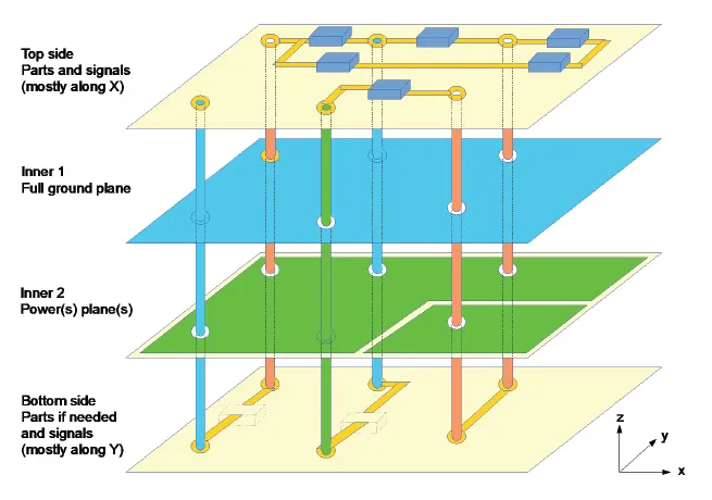
Layer stackup plays a critical role in maintaining signal quality. A typical design might include dedicated ground planes adjacent to signal layers to reduce noise. Additionally, differential signaling is often employed for critical data paths to enhance noise immunity. Adhering to guidelines in standards like IPC-2221B helps ensure consistent performance across high-frequency operations.
Power Integrity for Stable Operation
Power integrity ensures that voltage levels remain stable across the HDI PCB, even under fluctuating loads from X-ray generators and detectors. CT scanners demand high current for certain components, making it vital to minimize voltage drops and noise in power delivery networks. Wide power traces or planes reduce resistance, while decoupling capacitors placed near power pins suppress transients.
Simulation tools aligned with industry standards can predict and mitigate power distribution issues. Engineers often use low-inductance capacitors and optimize via placement to maintain clean power delivery. Following specifications in IPC-6012E for conductor spacing and thickness supports robust power integrity in high-reliability PCB designs.
Thermal Management in High-Power Systems
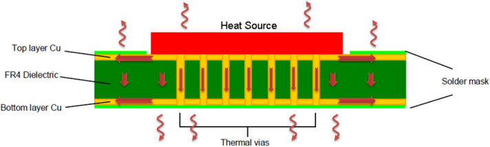
Thermal management is a significant concern in CT scanner PCBs due to the heat generated by high-power components. Excessive temperatures can degrade performance and shorten component lifespan. Effective designs incorporate heat sinks, thermal vias, and copper pours to dissipate heat away from critical areas.
Material selection also influences thermal performance. High-Tg substrates, as recommended by IPC-4101E, withstand elevated temperatures without deforming. Engineers must calculate thermal resistance paths and ensure airflow or active cooling aligns with system constraints. Proper thermal design prevents hotspots and maintains operational stability during extended scans.
EMC Shielding for Interference Control
Electromagnetic compatibility is crucial in medical environments where interference can disrupt sensitive equipment. CT scanner PCBs must minimize radiated emissions and resist external electromagnetic fields. Shielding techniques include enclosing critical circuits in metal cans or using ground planes to block interference.
Layout strategies, such as keeping high-frequency traces short and avoiding loops, reduce emission risks. Filtering components at board entry points further suppress noise. Compliance with IEC 60601-1-2, which outlines EMC requirements for medical electrical equipment, guides engineers in achieving safe and interference-free operation.
Best Practices for High-Reliability PCB Design in Medical Applications
Multilayer Design and HDI Technology
CT scanner PCBs often require multilayer configurations to accommodate dense circuitry and high-speed signals. A typical board might have 8 to 16 layers, separating power, ground, and signal paths for optimal performance. High-density interconnect (HDI) technology enables finer traces and smaller vias, supporting compact designs without sacrificing reliability.
Engineers should follow IPC-2226 for HDI design guidelines, ensuring manufacturability and signal integrity. Stackup symmetry prevents warpage, while blind and buried vias reduce signal path lengths. These practices are essential for meeting the spatial and performance demands of designs of the medical PCB.
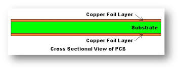
Material Selection for Durability
Choosing the right materials is fundamental for high-reliability PCBs in CT scanners. Substrates must resist moisture, thermal stress, and chemical exposure. Standards like IPC-4101E specify laminate properties, recommending materials with high glass transition temperatures and low dielectric loss for medical applications.
Copper thickness also matters, with heavier weights preferred for power planes to handle current loads. Surface finishes, as outlined in IPC-4552, protect against oxidation and ensure solderability during assembly. Selecting compliant materials minimizes risks in harsh operating conditions.
Design for Manufacturability and Testing
Designing for manufacturability reduces errors during production and assembly. Engineers must space components adequately for automated placement and soldering, following IPC-7351 for land pattern standards. Test points should be included for in-circuit testing to verify functionality post-assembly.
Automated optical inspection and X-ray testing, guided by IPC-A-600K, detect defects like voids in solder joints. Incorporating design for testability principles ensures that potential issues are identified early, maintaining the high reliability required for medical devices.
Manufacturing and Assembly Considerations
Manufacturing CT scanner PCBs demands precision to meet stringent quality standards. Processes must align with IPC-6012E, which defines performance criteria for rigid boards. Controlled environments prevent contamination, while advanced fabrication techniques ensure accurate trace widths and via drilling.
Assembly requires surface-mount technology for compact layouts, adhering to IPC J-STD-001 for soldering quality. Post-assembly inspection verifies component placement and joint integrity. These steps are critical to producing boards that withstand the operational stresses of medical imaging systems.
Testing and Validation for Regulatory Compliance
Testing is a cornerstone of high-reliability PCB design for CT scanners. Functional testing confirms signal and power integrity under real-world conditions. Environmental testing, based on the IEC 60068-2 series, assesses performance under temperature and humidity extremes.
Regulatory compliance is non-negotiable in medical applications. Standards like ISO 13485:2016 govern quality management for medical device manufacturing, while IEC 60601-1 outlines safety requirements. Validation must demonstrate adherence to these frameworks, ensuring patient safety and device efficacy. Thorough documentation supports audits and certification processes.
Conclusion
Designing PCBs for CT scanners is a complex endeavor that demands expertise in signal integrity, power integrity, thermal management, and EMC shielding. By adhering to industry standards and best practices, engineers can create high-reliability boards that meet the rigorous demands of medical imaging. From multilayer layouts to meticulous testing, every aspect of CT scanner PCB design contributes to device performance and patient safety. Understanding these principles equips professionals to tackle the challenges of medical PCB design, ensuring precision and reliability in critical healthcare technology.
FAQs
Q1: What are the key challenges in CT scanner PCB design?
A1: Signal integrity and power stability pose significant challenges in CT scanner PCB design. High-speed data from detectors requires precise impedance control to avoid errors. Thermal management is critical due to heat from power-intensive components. Additionally, EMC shielding must prevent interference in sensitive medical environments. Following standards like IPC-2221B ensures these issues are addressed effectively during the design phase.
Q2: How does thermal management impact medical PCB design?
A2: Thermal management directly affects the reliability of medical PCB design. Excessive heat can degrade components and cause system failures in CT scanners. Using thermal vias and high-Tg materials, as per IPC-4101E, helps dissipate heat. Proper layout and cooling solutions maintain operational stability. Effective thermal strategies prevent damage and ensure consistent performance during prolonged use.
Q3: Why is regulatory compliance crucial for high-reliability PCB in medical devices?
A3: Regulatory compliance ensures that high-reliability PCBs meet safety and performance standards for medical devices. Standards like ISO 13485:2016 and IEC 60601-1 define quality and safety requirements. Non-compliance risks patient harm and legal consequences. Thorough testing and documentation validate adherence, protecting users and manufacturers. Compliance builds trust in the device's reliability within healthcare settings.
Q4: What role does EMC shielding play in CT scanner PCB design?
A4: EMC shielding is vital in CT scanner PCB design to prevent electromagnetic interference. It minimizes emissions that could disrupt nearby equipment and protects against external fields. Techniques like ground planes and filters, guided by IEC 60601-1-2, ensure compatibility. Proper shielding maintains signal integrity and device safety. This is essential in medical environments with multiple electronic systems.
References
IPC-2221B — Generic Standard on Printed Board Design. IPC, 2012.
IPC-6012E — Qualification and Performance Specification for Rigid Printed Boards. IPC, 2020.
IPC-4101E — Specification for Base Materials for Rigid and Multilayer Printed Boards. IPC, 2017.
IPC-A-600K — Acceptability of Printed Boards. IPC, 2020.
IPC-7351 — Generic Requirements for Surface Mount Design and Land Pattern Standard. IPC, 2010.
IPC-4552 — Specification for Electroless Nickel/Immersion Gold (ENIG) Plating for Printed Circuit Boards. IPC, 2012.
IPC J-STD-001 — Requirements for Soldered Electrical and Electronic Assemblies. IPC, 2017.
ISO 13485:2016 — Medical Devices - Quality Management Systems - Requirements for Regulatory Purposes. ISO, 2016.
IEC 60601-1 — Medical Electrical Equipment - Part 1: General Requirements for Basic Safety and Essential Performance. IEC, 2012.
IEC 60601-1-2 — Medical Electrical Equipment - Part 1-2: General Requirements for Basic Safety and Essential Performance - Collateral Standard: Electromagnetic Disturbances - Requirements and Tests. IEC, 2014.
IEC 60068-2 — Environmental Testing - Part 2: Tests. IEC, various dates.
IPC-2226 — Sectional Design Standard for High Density Interconnect (HDI) Printed Boards. IPC, 2006.


