Introduction
LED lighting applications demand reliable thermal performance to maintain efficiency and longevity. Printed circuit boards serve as the foundation for mounting high-power LEDs, where heat generated from forward voltage drops and junction temperatures must dissipate effectively. Choosing between 1oz and 2oz copper thicknesses directly influences PCB heat dissipation capabilities in these systems. Electrical engineers often face trade-offs in LED PCB design when balancing thermal management with manufacturability and cost. This article compares the thermal performance of 1oz versus 2oz copper PCBs, focusing on practical implications for LED lighting. Factory insights reveal how copper weight impacts overall board reliability under sustained operation.
Understanding Copper Weight in PCBs
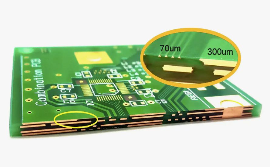
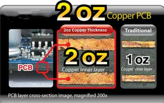
Copper weight, measured in ounces per square foot, defines the thickness of the copper foil layers on a PCB. A 1oz copper layer corresponds to approximately 35 microns thick, while 2oz doubles that to about 70 microns. This thickness affects electrical conductivity, mechanical strength, and crucially, thermal properties in LED lighting PCBs. Standard manufacturing processes laminate these foils to the substrate, with heavier weights requiring adjusted etching and plating steps. Engineers specify copper weight based on current demands and heat loads typical in LED drivers and arrays. IPC-2221 provides generic guidelines for selecting copper thickness in board design to ensure performance margins.
In LED PCB design, copper acts as a primary heat spreader due to its high thermal conductivity of around 400 W/mK. Thinner 1oz layers suffice for low-power indicators, but high-brightness LEDs in lighting fixtures generate watts of heat per chip. Factory-driven validation confirms that copper weight influences lateral heat spreading before transfer to ambient air or heatsinks. Variations in weight also impact via plating, where thermal vias bridge layers for vertical conduction. Selecting the right weight aligns with application needs, avoiding hotspots that degrade phosphor conversion or solder joints.
Thermal Management Challenges in LED Lighting
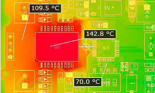
LEDs convert over 70 percent of input power to heat, raising junction temperatures that reduce luminous efficacy and accelerate degradation. PCB heat dissipation becomes critical in dense arrays for streetlights, automotive headlights, or indoor fixtures, where airflow is limited. Junction-to-ambient thermal resistance must stay low to keep operating temperatures below 100 degrees Celsius for optimal lifespan. Poor dissipation leads to color shifts, droop in output, and premature failures in LED lighting PCBs. Engineers model these using finite element analysis, factoring substrate properties and copper planes.
Substrate materials like FR4 offer limited in-plane conductivity around 0.3 W/mK, relying on copper for spreading. Convection and radiation dominate cooling, but copper thickness determines how uniformly heat distributes across the board. High-power LEDs, often 1 to 5 watts each, cluster on boards, amplifying local temperatures without adequate spreading. Factory testing simulates real-world loads to verify dissipation paths. Integrating thermal vias and pours enhances performance, yet copper weight sets the baseline effectiveness.
Mechanisms of Heat Dissipation in Copper PCBs
Heat from LED die flows through the package to the PCB copper, spreading laterally before vertical conduction via vias or dielectric to the opposite side. Copper's isotropic conductivity excels in-plane spreading, with thermal resistance inversely proportional to thickness and area. For a given hotspot, thicker copper reduces spreading resistance, lowering peak temperatures over larger distances. This effect proves vital in LED PCB design, where multiple emitters share copper planes. Simulations show 2oz layers achieving more uniform isotherms compared to 1oz under identical loads.
The via thermal resistance remains similar between 1oz and 2oz boards, as plating thickness stays constant around 18 to 25 microns per IPC specifications. Thus, benefits accrue mainly from surface copper planes acting as heat sinks. In multilayer boards, inner layers contribute less due to dielectric barriers, emphasizing outer layer weight. Factory processes control copper uniformity to IPC-6012 standards, ensuring consistent thermal paths. Radiation emissivity of copper surfaces also aids dissipation, though oxidation must be managed.
1oz vs 2oz Copper: Thermal Performance Comparison
1oz copper PCBs handle moderate heat loads effectively in low-to-medium power LED applications, offering cost-effective solutions with standard etching capabilities. Their thinner profile suits fine-pitch traces under 0.15 mm, common in compact lighting modules. However, under high currents above 1 ampere per trace, temperature rises accelerate, limiting use in dense high-power arrays. PCB heat dissipation relies on larger pour areas to compensate, increasing board size undesirably. Engineers reference IPC-2152 charts, which plot allowable current versus temperature rise for 1oz traces, guiding conservative designs.
In contrast, 2oz copper PCBs excel in 2oz copper PCB thermal performance for demanding LED lighting scenarios. The doubled thickness halves in-plane thermal resistance for the same footprint, spreading heat farther and reducing deltas by notable margins. This allows narrower traces for equivalent dissipation, densifying layouts without hotspots. Applications like 50-watt floodlights benefit, as 2oz sustains higher power densities. Factory data aligns with standards, showing improved reliability in accelerated life tests.
- Thickness (μm): 1oz ≈ 35; 2oz ≈ 70
- Heat Spreading Distance: 1oz shorter; 2oz longer
- Current Capacity (same width): 1oz baseline; 2oz approximately double
- Temperature Rise (high load): 1oz higher; 2oz lower
- LED Suitability: 1oz for low–medium power; 2oz for high-power arrays
Trade-offs include challenging etching for features below 0.2 mm and increased warpage risk from differential expansion. Heavier copper demands slower etch rates and stronger developers in production.
Best Practices for LED PCB Design with Copper Weight Selection
Start with power budget analysis to determine peak heat dissipation needs per square centimeter. For currents exceeding IPC-2152 limits for 1oz, specify 2oz on power planes. Incorporate thermal vias arrays under LEDs, tented or filled, spaced 1 to 2 mm apart for vertical paths. Use copper pours covering 70 percent or more of the board surface, connected via spokes to avoid isolation. Silkscreen or soldermask over bare copper enhances emissivity without impeding convection.
Multilayer designs pair 2oz outer layers with 1oz inners for balanced cost and performance. Simulate with tools validating against standards to predict junction temperatures. Factory recommendations include symmetric stackups to minimize bow and twist per IPC-A-600. For edge-lit or COB LEDs, prioritize 2oz to leverage spreading. Test prototypes under forced air mimicking fixtures.
Manufacturing Insights and Quality Control
Producing 2oz copper PCBs requires panel electroplating for uniform buildup, contrasting electrodeposited 1oz foils. Etch factor worsens with thickness, necessitating compensation in CAM software for trapezoidal profiles. Lamination pressures adjust to prevent voids under heavy foils. Post-etch cleaning removes undercuts, critical for LED solderability. IPC-6012E qualifies boards for thermal cycling, ensuring no delamination in LED thermal profiles.
Warpage control uses controlled impedance stackups and bake cycles per J-STD-020. Electrical testing verifies continuity under heat, while AOI detects defects amplified by thickness. These steps guarantee 2oz copper PCB thermal performance in production volumes.
Conclusion
In LED lighting PCBs, 2oz copper outperforms 1oz in PCB heat dissipation, particularly for high-power designs requiring robust spreading. While 1oz suffices for simpler applications, 2oz enables compact, reliable systems aligned with engineering demands. Adhering to IPC guidelines optimizes selection, balancing thermal benefits against fabrication challenges. Engineers achieve superior LED PCB design by integrating these insights into workflows. Factory-aligned practices ensure consistent performance in real-world deployments.
FAQs
Q1: What improves 2oz copper PCB thermal performance in LED lighting?
A1: Thicker 2oz copper layers enhance lateral heat spreading due to increased cross-sectional area, reducing peak temperatures around high-power LEDs. This lowers junction-to-ambient resistance compared to 1oz, supporting higher wattages without external cooling. Design with pours and vias maximizes benefits, per industry standards. Factory processes ensure uniformity for reliable dissipation.
Q2: How does copper thickness impact LED PCB design for heat dissipation?
A2: In LED PCB design, thicker copper like 2oz doubles current capacity and improves thermal conductivity for better PCB heat dissipation. It spreads heat from clusters of emitters, preventing droop and failures. Balance with etching limits and stackup symmetry. Simulations validate choices against thermal loads.
Q3: When should electrical engineers choose 2oz over 1oz for LED lighting PCBs?
A3: Opt for 2oz copper PCBs when LED arrays exceed 2 watts per chip or currents surpass 1oz limits, prioritizing thermal performance. Ideal for automotive or industrial lighting with limited airflow. Assess via IPC charts for temperature rises. Trade higher cost for longevity gains.
Q4: What role do standards play in PCB heat dissipation for LEDs?
A4: Standards like IPC-2152 guide trace sizing for thermal rises in LED lighting PCBs. They ensure designs handle dissipation without exceeding safe limits. Factory compliance verifies copper weight effects on performance.
References
IPC-2221B — Generic Standard on Printed Board Design. IPC, 2009
IPC-2152B — Standard for Determining Current Carrying Capacity in Printed Board Design. IPC, 2009
IPC-6012E — Qualification and Performance Specification for Rigid Printed Boards. IPC, 2015
IPC-A-600K — Acceptability of Printed Boards. IPC, 2020


