Introduction
In the realm of power electronics, the demand for reliable and efficient components continues to grow. Thick copper FR-4 PCBs, also known as heavy copper PCBs, have emerged as a critical solution for applications requiring high current capacity and robust thermal management. These specialized boards are designed to handle substantial electrical loads, making them ideal for power supplies, motor drives, and renewable energy systems. Their construction, based on the widely used FR-4 substrate with enhanced copper thickness, offers a balance of performance and cost effectiveness. This article explores the technical foundations of thick copper PCBs, their benefits in high current scenarios, and best practices for design and implementation. Aimed at electrical engineers, the content provides precise insights into leveraging FR-4 power PCBs for demanding applications.
What Are Thick Copper FR-4 PCBs and Why Do They Matter
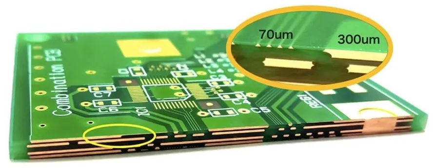
Thick copper FR-4 PCBs are printed circuit boards that utilize the standard FR-4 epoxy laminate as a base material but feature significantly thicker copper layers. Typically, standard PCBs have copper thicknesses ranging from 0.5 to 1 ounce per square foot. In contrast, heavy copper PCBs start at 3 ounces per square foot and can go up to 20 ounces or more, depending on the application requirements. This increased thickness directly enhances the PCB current rating, allowing the board to conduct higher electrical currents without overheating or degrading.
The importance of high current PCBs lies in their ability to support power electronics where substantial energy transfer is necessary. Applications such as industrial inverters, electric vehicle chargers, and high power LED systems rely on these boards to maintain stability under load. Additionally, the enhanced copper layers improve thermal management in PCBs by dissipating heat more effectively, reducing the risk of hotspots and component failure. For engineers working on FR-4 for power supplies, understanding the role of heavy copper is essential to ensure reliability and efficiency in high stress environments.
Technical Principles Behind Thick Copper PCBs
The core advantage of thick copper PCBs stems from their ability to handle elevated current densities. Electrical current flowing through a conductor generates heat due to resistance, as described by Joule's law. In standard PCBs, thin copper layers can overheat under high current, leading to trace damage or delamination. By increasing copper thickness, the cross sectional area of the conductor grows, reducing resistance and thus minimizing heat generation. This principle directly boosts the high current PCB performance.
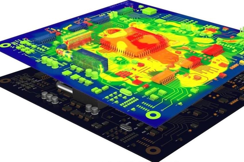
Moreover, thermal management in PCBs benefits significantly from heavy copper. Copper is an excellent thermal conductor, and thicker layers provide a larger pathway for heat to spread across the board and dissipate into the surrounding environment or attached heat sinks. According to widely accepted industry guidelines, such as those outlined in IPC-2152, the current carrying capacity of a trace is directly proportional to its width and thickness. Therefore, thick copper FR-4 PCBs can sustain higher currents without exceeding safe temperature limits.
Another critical factor is the dielectric strength of the FR-4 material. While FR-4 is not inherently designed for extreme thermal or electrical stress, its flame retardant properties and mechanical stability make it suitable for many power applications when paired with heavy copper. However, engineers must consider the glass transition temperature of FR-4, typically around 130 to 140 degrees Celsius, to avoid material degradation in high heat scenarios.
Related Reading: Thick PCB Materials: High Speed applications
Benefits of Thick Copper FR-4 PCBs in Power Electronics
Thick copper FR-4 PCBs offer several advantages for power electronics, making them a preferred choice for high current applications. First, their enhanced PCB current rating allows for the design of compact boards that can handle significant power without requiring multiple layers or oversized traces. This efficiency reduces overall board size and material costs while maintaining performance.
Second, the improved thermal management in PCBs reduces the need for additional cooling mechanisms in many designs. By spreading heat more evenly across the board, thick copper minimizes thermal stress on components, extending their lifespan. This is particularly valuable in FR-4 power PCB designs for power supplies, where consistent operation under load is critical.
Third, heavy copper PCBs provide mechanical strength. The thicker copper layers add rigidity to the board, reducing the risk of cracking or warping during assembly or operation. This durability is essential in harsh environments, such as automotive or industrial settings, where vibration and temperature fluctuations are common.
Finally, thick copper FR-4 PCBs maintain compatibility with standard manufacturing processes. Unlike exotic materials or substrates, FR-4 with heavy copper can be fabricated using conventional equipment, adhering to standards like IPC-6012E for rigid printed boards. This ensures accessibility for engineers and designers seeking reliable solutions without specialized production lines.
Design Considerations for High Current PCBs
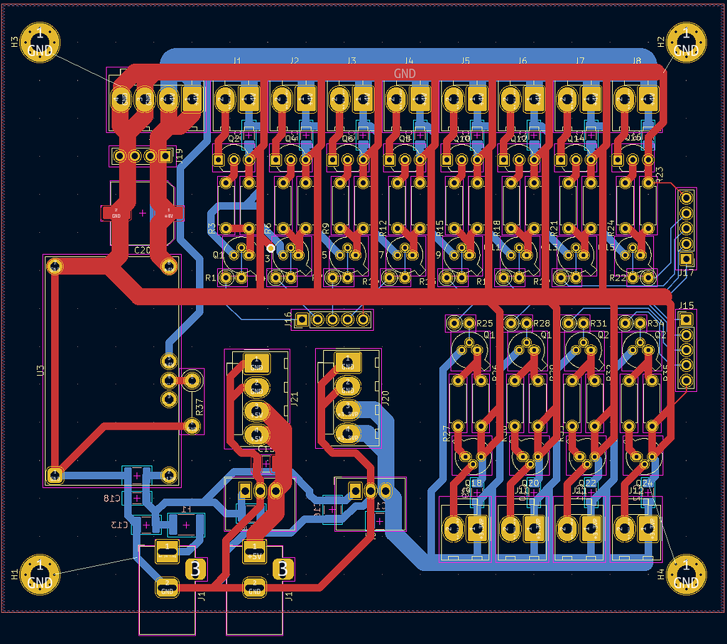
Designing thick copper FR-4 PCBs for high current applications requires careful attention to several factors. Trace width and spacing must be calculated based on the expected current load, following guidelines from standards such as IPC-2152. This standard provides charts and formulas to determine safe current carrying capacity based on copper thickness, ambient temperature, and trace dimensions.
Layer stackup is another critical aspect. While single or double layer boards with thick copper may suffice for simpler designs, complex power electronics often benefit from multilayer configurations. In such cases, ensuring proper via design is vital to maintain current flow between layers without creating bottlenecks or heat buildup. Standards like IPC-A-600K offer detailed criteria for acceptable via plating and construction.
Thermal management in PCBs also demands strategic placement of components. High power components should be positioned near thick copper traces or planes to facilitate heat dissipation. Additionally, incorporating thermal vias can enhance heat transfer to other layers or external heat sinks. Engineers must balance these design choices with the limitations of FR-4 material to prevent exceeding its thermal thresholds.
Lastly, manufacturing tolerances must be considered. Thick copper layers can introduce challenges during etching and lamination, potentially leading to uneven trace profiles or undercutting. Adhering to specifications in IPC-6012E helps mitigate these risks, ensuring the final board meets performance expectations.
Related Reading: Building a High Current Power Supply with Thick Copper PCBs: A Step by Step Guide
Practical Solutions for Implementing Thick Copper PCBs
When integrating thick copper FR-4 PCBs into power electronics, engineers can adopt several best practices to optimize performance. Start by defining the current requirements of the application and selecting an appropriate copper thickness. For moderate loads, 3 to 6 ounces per square foot may be sufficient, while extreme high current PCB designs might require 10 ounces or more.
Next, prioritize thermal management strategies. Use wide copper traces and large copper planes to distribute heat effectively. If additional cooling is needed, consider attaching heat sinks directly to copper areas with high thermal conductivity. Thermal vias, strategically placed near heat generating components, can further improve dissipation.
Testing and validation are also essential. Simulate the design under expected operating conditions to identify potential thermal or electrical issues. Standards like IPC-2152 provide methodologies for such evaluations, ensuring the design aligns with safe operating limits. Physical prototypes should be tested for temperature rise and current handling to confirm theoretical predictions.
Finally, collaborate with manufacturing partners to verify process capabilities for heavy copper PCB production. Ensure that the chosen copper thickness and design features comply with standards such as IPC-A-600K for acceptability of printed boards. Clear communication of specifications prevents costly errors during fabrication.
Challenges and Limitations of FR-4 in High Power Applications
While thick copper FR-4 PCBs are highly effective for many power electronics, they are not without limitations. The primary challenge lies in the thermal properties of FR-4 material. Its relatively low glass transition temperature restricts its use in applications exceeding 130 to 140 degrees Celsius for prolonged periods. Beyond this range, the material may soften or degrade, compromising board integrity.
Additionally, FR-4 has a lower thermal conductivity compared to alternative substrates like metal core PCBs. While thick copper mitigates this to an extent, extremely high power applications may still require supplemental cooling solutions or different base materials. Engineers must evaluate whether FR-4 for power supplies remains viable under peak load conditions.
Manufacturing heavy copper PCBs also presents challenges. Thicker copper layers increase etching difficulty, potentially leading to inconsistent trace widths or defects. Adhering to standards like IPC-6012E ensures quality, but it may raise production costs due to specialized processes or additional quality checks.
Conclusion
Thick copper FR-4 PCBs stand as a robust solution for high current capacity in power electronics, balancing performance with cost efficiency. Their ability to handle substantial electrical loads and provide effective thermal management makes them indispensable for applications ranging from power supplies to industrial systems. By understanding the technical principles behind high current PCBs and following industry standards, engineers can design reliable and durable boards. Careful consideration of design parameters, thermal constraints, and manufacturing processes ensures optimal outcomes. For projects requiring FR-4 power PCBs, leveraging heavy copper technology offers a proven path to success in demanding environments.
FAQs
Q1: What makes thick copper PCBs suitable for high current applications?
A1: Thick copper PCBs, often starting at 3 ounces per square foot, offer a larger cross sectional area for current flow, reducing resistance and heat generation. This enhances their PCB current rating, making them ideal for power electronics like inverters and motor drives. Standards like IPC-2152 provide guidelines to ensure safe current handling.
Q2: How does thermal management in PCBs benefit from heavy copper?
A2: Heavy copper PCB designs improve thermal management by providing better heat dissipation through thicker copper layers. Copper's high thermal conductivity spreads heat away from critical components, reducing hotspots. This is crucial for FR-4 power PCB applications, preventing thermal stress and extending component life.
Q3: What are the limitations of using FR-4 for power supplies with thick copper?
A3: FR-4 for power supplies has thermal limitations due to its glass transition temperature of 130 to 140 degrees Celsius. Prolonged exposure to higher temperatures can degrade the material. While thick copper helps, extreme conditions may require alternative substrates for sustained performance.
Q4: How can engineers ensure reliability in high current PCB designs?
A4: Engineers can ensure reliability in high current PCB designs by following standards like IPC-2152 for current capacity and IPC-6012E for manufacturing quality. Proper trace sizing, thermal via placement, and testing under load conditions are critical steps to achieve consistent performance in power applications.
References
IPC-2152 — Standard for Determining Current Carrying Capacity in Printed Board Design. IPC, 2009.
IPC-6012E — Qualification and Performance Specification for Rigid Printed Boards. IPC, 2020.
IPC-A-600K — Acceptability of Printed Boards. IPC, 2020.


