Introduction
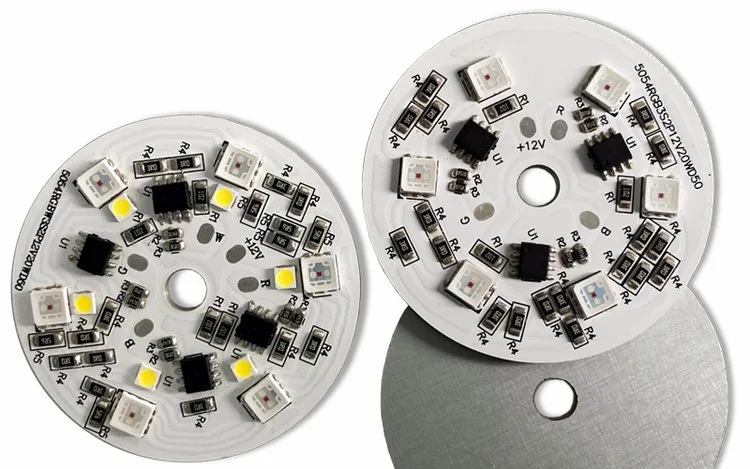
Aluminum printed circuit boards (PCBs), commonly known as metal core PCBs (MCPCBs), have long been recognized for their exceptional thermal management capabilities. Traditionally, these boards are deployed in high power applications like LED lighting, automotive power modules, and industrial motor controls, where efficient heat dissipation is paramount. However, with the increasing miniaturization of electronic devices and the convergence of power and signal processing, there is a growing interest in leveraging aluminum PCBs for high frequency aluminum PCB applications, including microwave circuits. This presents a unique set of design considerations that move beyond conventional thermal management, demanding a meticulous approach to aluminum PCB impedance control and aluminum PCB signal integrity. This overview delves into the critical aspects of designing aluminum PCBs to meet the stringent demands of high-frequency and aluminum PCB microwave applications.
What is an Aluminum PCB and Its Initial Use Case
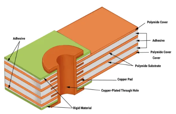
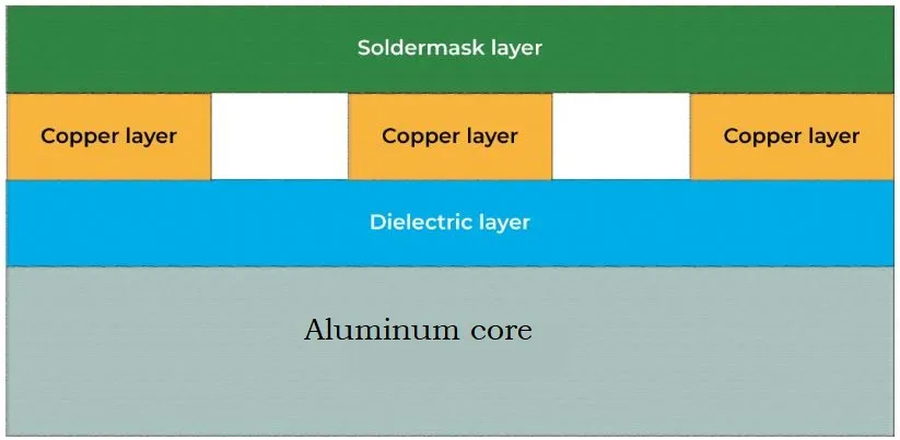
An aluminum PCB typically consists of a copper circuit layer, a thin dielectric insulating layer (often called the thermal interface material), and an aluminum base layer. The aluminum base serves as a robust mechanical support and, most importantly, as an excellent heat sink, rapidly drawing heat away from components. This structure provides superior thermal conductivity compared to traditional FR-4 PCBs, significantly extending component lifespan and improving system reliability in high-heat environments.
While their thermal prowess is undeniable, the application of aluminum PCBs in high frequency domains introduces complexities not typically encountered in their low frequency, high power counterparts. The conductive aluminum core, interacting with sensitive high-frequency signals, necessitates a re evaluation of fundamental PCB design principles to ensure predictable electrical performance and robust aluminum PCB signal integrity.
Related Reading: Aluminum PCBs: An Essential Solution for High-Performance Electronics
Unique Challenges for High-Frequency Aluminum PCB Design
Integrating high-frequency signals onto an aluminum PCB structure presents several distinct challenges that must be meticulously addressed during the design phase.
Signal Integrity and EMI Concerns
The large, conductive aluminum base can significantly influence electromagnetic fields around signal traces.
- Reflections and Loss: Impedance mismatches, often exacerbated by the dielectric material properties and the proximity to the conductive aluminum, can lead to increased signal reflections and insertion loss.
- Crosstalk: The close proximity of signal traces to the aluminum core, combined with less controlled dielectric properties, can enhance crosstalk between adjacent traces, degrading signal quality.
- EMI Radiation: While the aluminum base acts as a good ground plane, improperly designed signal return paths can lead to unintended loop areas, contributing to electromagnetic interference (EMI) radiation or susceptibility.
Impedance Control Difficulties
Achieving precise aluminum PCB impedance control is one of the most critical challenges.
- Dielectric Thickness and Consistency: Standard aluminum PCBs often use a relatively thick thermal dielectric layer (e.g., 50–150 micrometers) with properties not optimized for RF. Even small variations in this thickness or its dielectric constant (Dk) can lead to significant impedance fluctuations for microstrip or stripline configurations.
- Dielectric Constant (Dk) and Dissipation Factor (Df): The dielectric materials used in conventional aluminum PCBs are typically chosen for thermal performance and electrical insulation, not necessarily for stable Dk and low Df at high frequencies. A high Df contributes to signal loss, while a variable Dk complicates impedance prediction.
- Proximity to Ground: The immediate proximity of the signal layer to the vast aluminum ground plane, separated only by a thin dielectric, means that trace width and dielectric properties become extremely sensitive parameters for achieving a target impedance, such as 50 ohms.
Thermal Dielectric Material Considerations
The thermal dielectric layer is the heart of an aluminum PCB, but its characteristics are a double-edged sword for high-frequency design.
- Dk and Df at High Frequencies: As mentioned, many thermal dielectrics exhibit higher Dk and Df values, and greater variability with frequency and temperature, compared to specialized RF laminates. These properties directly impact signal propagation speed and loss.
- Thickness Uniformity: Maintaining a very thin and uniform dielectric layer across the entire board is critical for consistent impedance. Achieving this with thermally optimized materials designed for robustness can be challenging in manufacturing.
- Adhesion and Reliability: The bond between the copper foil, dielectric, and aluminum base must remain robust under thermal cycling, but also electrically stable for high frequency.
Related Reading: Aluminum PCBs: Thermal Management for High Power Electronics
Key Design Considerations for High-Frequency Aluminum PCBs
To overcome these challenges, a specialized design approach is essential for high frequency aluminum PCB applications.
1. Selection of Advanced Dielectric Materials
The most crucial step is to select a dielectric insulating layer specifically engineered for high-frequency performance while still offering adequate thermal conductivity.
- Low and Stable Dielectric Constant (Dk): Choose materials with a Dk that is low and exhibits minimal variation with frequency and temperature. This ensures predictable impedance and consistent signal propagation speeds. For example, materials with Dk values below 4.0 are often preferred for RF.
- Low Dissipation Factor (Df): A low Df minimizes signal loss, which is critical for maintaining signal strength over longer traces and at higher frequencies. Values below 0.005 are generally considered good for RF applications.
- Ultra-Thin Dielectric Layer: Using the thinnest possible dielectric layer that provides sufficient electrical insulation and breakdown voltage is crucial. A thinner dielectric allows for wider traces for a given impedance, which helps reduce resistive losses, and improves thermal transfer to the aluminum core.
- CTE Matching: Ideally, the CTE of the dielectric material should be closely matched to that of copper and aluminum to minimize stress and improve reliability during thermal cycling.
2. Precise Impedance Control Design
Achieving tight aluminum PCB impedance control requires careful calculation and validation.
- Transmission Line Structures: Microstrip lines are the most common configuration on aluminum PCBs. The characteristic impedance is highly sensitive to trace width, the Dk of the dielectric, and the dielectric thickness.
- Simulation and Modeling: Utilize electromagnetic field solvers and impedance calculators specifically designed for microstrip lines on metal core substrates. These tools help predict impedance based on material properties and trace geometry.
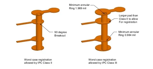
- Manufacturing Tolerances: Account for manufacturing tolerances in trace width and dielectric thickness. Designers must work closely with fabricators to understand their capabilities and ensure the design is manufacturable to the required impedance tolerance. IPC-2141, Controlled Impedance Circuit Boards and High Speed Logic Design, provides general guidelines for impedance control.
3. Optimized Layer Stack-up and Grounding
The simplicity of a single layer aluminum PCB (signal layer on top of dielectric and aluminum ground) is advantageous for thermal management but requires careful RF design.
- Robust Ground Plane: The aluminum base provides an excellent, large area ground plane. Ensure strong, low impedance connections to this ground plane for all components and signal return paths.
- Return Path Management: Critical high-frequency signals must have clearly defined, continuous return paths directly beneath their traces on the ground plane. Any discontinuity in the return path will create a large loop area, leading to impedance mismatches and EMI.
- Shielding: The aluminum core naturally provides a degree of EMI shielding, but good design principles for trace routing and component placement are still essential to prevent internal noise generation.
4. Via Design and Interconnections
Vias are points of discontinuity and must be carefully designed in high-frequency aluminum PCBs.
- Ground Vias: Place an adequate number of ground vias (sometimes referred to as thermal vias when their primary function is thermal) close to component pads and along transmission lines to ensure a low inductance connection to the aluminum ground plane.
- Signal Vias: Minimize the use of signal vias, and when necessary, optimize their size and surround them with ground vias to control impedance and minimize reflections.
5. Component Placement and Layout
Strategic component placement is always critical, but even more so for high-frequency circuits on aluminum.
- Minimize Trace Lengths: Keep high-frequency signal traces as short as possible to reduce signal loss and parasitic effects.
- Avoid Stubs: Eliminate or minimize stubs on transmission lines, as they act as resonant structures at high frequencies.
- Isolation: Separate high-frequency circuits from noisy digital or power sections to prevent coupling.
- Thermal Management Integration: Leverage the aluminum core's thermal properties by placing heat generating components directly above the aluminum base, ensuring good thermal contact through the thin dielectric.
Manufacturing and Verification
Successfully fabricating high frequency aluminum PCB designs requires close collaboration with the manufacturer and stringent quality control.
- Fabrication Capabilities: Verify the fabricator's ability to consistently produce boards with the specified ultra-thin, low-loss dielectric layers and tight impedance tolerances.
- Impedance Testing: Time Domain Reflectometry (TDR) testing is crucial to verify the actual characteristic impedance of transmission lines on the manufactured boards. This ensures that the fabricated board meets the electrical design specifications. IPC-6012E, Qualification and Performance Specification for Rigid Printed Boards, outlines performance requirements for rigid PCBs, which can be adapted.
- Material Characterization: Reliable material data from the laminate supplier, including measured Dk and Df values at relevant frequencies, is essential for accurate design and simulation.
Conclusion
Designing aluminum PCB microwave applications and other high-frequency circuits demands a nuanced approach that transcends traditional thermal considerations. By selecting specialized dielectric materials with stable, low Dk and Df values, implementing precise aluminum PCB impedance control techniques, and meticulously managing grounding and signal return paths, engineers can harness the thermal benefits of aluminum while achieving robust aluminum PCB signal integrity. Close collaboration with manufacturers and rigorous verification through simulation and testing are crucial to realizing high performance, reliable, and cost-effective high frequency aluminum PCB designs for the next generation of electronic systems.
FAQs
Q1: What are the main challenges for aluminum PCBs in high-frequency applications?
A1: The main challenges for aluminum PCBs in high-frequency applications include achieving precise aluminum PCB impedance control due to the dielectric layer's properties, mitigating signal integrity issues like reflections and crosstalk, and managing EMI because of the large conductive aluminum base.
Q2: How does the dielectric layer influence high-frequency performance on an aluminum PCB?
A2: The dielectric layer critically influences high-frequency performance on an aluminum PCB through its dielectric constant (Dk) and dissipation factor (Df). A low, stable Dk ensures predictable impedance, while a low Df minimizes signal loss, both essential for aluminum PCB signal integrity in aluminum PCB microwave applications.
Q3: Why is careful impedance control particularly important for high-frequency aluminum PCBs?
A3: Careful impedance control is particularly important for high-frequency aluminum PCBs because signals become highly sensitive to impedance mismatches at these frequencies, leading to reflections, signal loss, and degraded performance. The thin dielectric and conductive aluminum base make impedance highly sensitive to design parameters.
Q4: Can standard aluminum PCBs be used for high-frequency circuits without modification?
A4: Standard aluminum PCBs are generally not suitable for high-frequency circuits without modification. Their dielectric materials are often optimized for thermal conductivity and insulation, not for low Dk and Df stability required for good aluminum PCB signal integrity and predictable aluminum PCB impedance control at high frequencies.
References
IPC-2141 — Controlled Impedance Circuit Boards and High Speed Logic Design. IPC.
IPC-2221A — Generic Standard on Printed Board Design. IPC, 2003.
IPC-6012E — Qualification and Performance Specification for Rigid Printed Boards. IPC, 2017.