Introduction to AOI Programming
Automated Optical Inspection (AOI) plays a key role in PCB quality control. Electrical engineers rely on AOI to detect defects early in manufacturing. This AOI programming tutorial simplifies the process for beginners. It covers AOI machine setup, AOI software guide, AOI program creation, and AOI test program validation.
AOI systems use cameras and software to inspect PCBs for issues like missing components or poor solder joints. Proper programming ensures reliable results aligned with industry standards. Factories use AOI post-SMT placement and reflow to maintain high yields. This guide provides structured steps based on established practices.
Electrical engineers benefit from understanding AOI program creation. It reduces false calls and optimizes inspection. Follow these steps to build effective AOI test programs.
What Is AOI and Why It Matters for Electrical Engineers
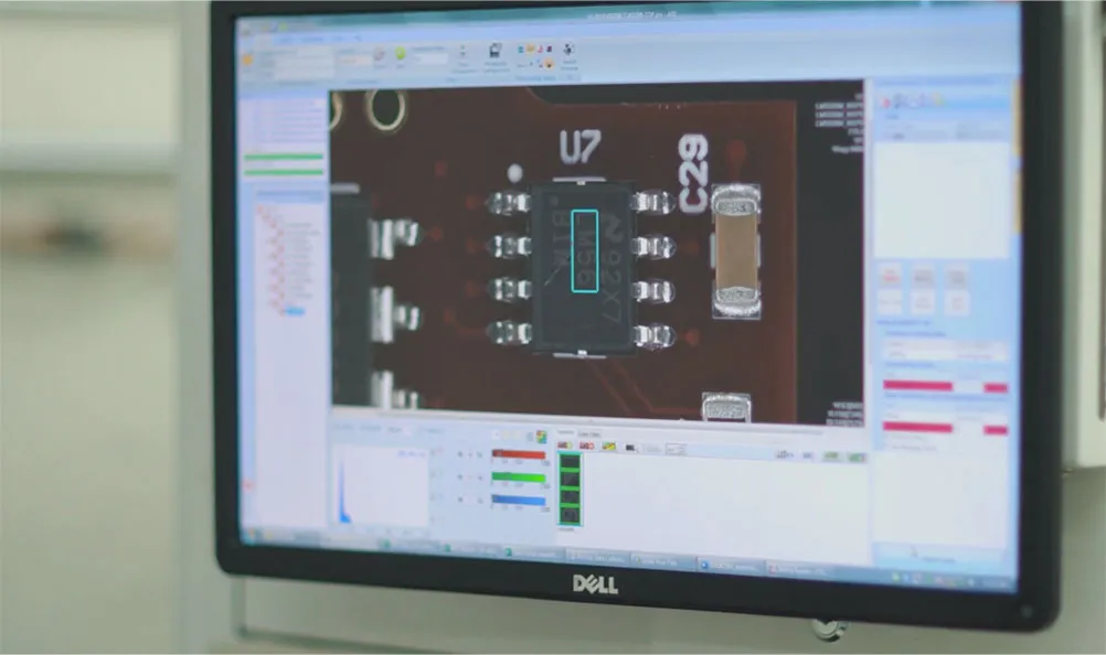
AOI stands for Automated Optical Inspection. It scans PCBs with high-resolution cameras. Software analyzes images against programmed criteria. This method detects defects faster than manual inspection.
AOI matters in PCB manufacturing because it ensures compliance with quality standards. Electrical engineers design circuits that demand precision. Defects like bridging or opens can cause failures in operation. AOI catches these issues before assembly advances. For real-world examples of defects AOI systems catch in production, see our visual guide to common PCB defects detected by AOI equipment.
Standards define acceptability criteria. IPC-A-600 specifies bare board visual standards. IPC-A-610 covers assembled boards. These guide AOI programming. Without proper AOI software guide, inspections miss critical faults. Factories report higher first-pass yields with tuned AOI programs.
For electrical engineers, AOI provides data on process variations. It links design to manufacturing outcomes. This insight improves future layouts.
Technical Principles of AOI Programming Systems
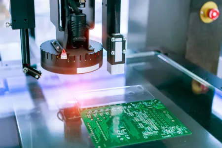
AOI relies on image acquisition and analysis. Multiple cameras capture 2D or 3D images. Lighting systems highlight features like solder fillets.
Software processes images using algorithms. Edge detection identifies component outlines. Pattern matching verifies positions. Color analysis checks solder color.
Key parameters include resolution and field of view. Higher resolution detects smaller defects. Standards like IPC-9716 outline AOI process control requirements. This includes calibration and threshold settings.
Fiducial marks align the system. They reference board position. Algorithms compare actual images to reference data from CAD or golden boards.
IPC classes define tolerance levels. Class 2 suits general electronics. Class 3 demands tighter controls for high-reliability applications.
AOI Machine Setup Essentials
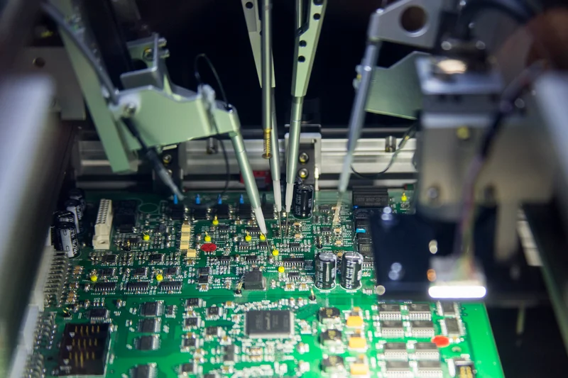
Start with clean environment. Dust affects image quality. Position the AOI machine on stable surface.
Calibrate cameras and lights. Follow manufacturer guidelines for focus. Verify conveyor speed matches line rate.
Load board handling fixtures. Ensure secure grip without damage. Align fiducials for accurate teaching.
IPC-9716 requires documented setup procedures. Record parameters like exposure time and gain.
Test with blank board. Confirm no false triggers.
AOI Programming Tutorial: Step-by-Step Guide
This AOI programming tutorial breaks down AOI program creation. Use CAD data, Gerber files, and BOM.
Step 1: Import Design Data for AOI Programming
Load Gerber, drill files, and netlist into AOI software. This creates reference library. Match layers to board stackup.
Verify component libraries. Update for custom parts.
Step 2: Teach Fiducials and Board Outline
Scan golden board. Select two to four fiducials. Software computes alignment.
Define board edges and cutouts. Exclude non-inspect areas like heat sinks.
Step 3: Program Component Inspection
For each part, set presence/absence check. Define polarity marks. Use IPC-A-610 criteria for placement offset.
Set tolerances: X/Y shift, rotation. Typical values follow class requirements.
Step 4: Configure Solder Joint Inspection
Program for pre-reflow and post-reflow. Check pad coverage and fillet height visually.
IPC J-STD-001G defines solder criteria. Adjust thresholds for bridges, voids.
Use 3D profiling if available for height measurement.
Step 5: Set Defect Classification
Categorize defects: critical, major, minor. Assign false call limits.
IPC-9716 guides detectability and resolution. [1]
Step 6: Run Golden Board Teach
Inspect known good board. Auto-generate reference images. Optimize lighting for contrast.

Best Practices for AOI Software Guide and Program Optimization
Align programs with production volume. Use rule-based programming for flexibility.Validate with first article inspection. Compare AOI calls to manual checks.Monitor false call rates. Adjust thresholds iteratively. IPC-9716 emphasizes process control. Integrate with MES for traceability. Store programs per panel size.Train operators on software interface. Document changes for repeatability.For multi-layer boards, inspect inner layers via bare board AOI per IPC-6012. When surface inspection alone is insufficient, complement your AOI program with X-ray methods for hidden solder joints.
AI Tips for Optimization Modern AOI software incorporates machine learning to analyze historical data, automatically suggesting threshold adjustments and predicting process drifts. Generative AI tools can even auto-create initial inspection regions from CAD data, reducing programming time by up to 70%.
Threshold Tuning Guide
| Defect Type | Class 2 Tolerance | Class 3 Tolerance | AI-Assisted Adjustment Tip |
|---|---|---|---|
| Component Offset (X/Y) | ±0.10 mm | ±0.05 mm | ML model learns from 100+ good/bad boards |
| Rotation | ±5° | ±2° | Auto-adjust based on fiducial variance |
| Solder Bridge | Height < 0.05 mm | Height < 0.03 mm | 3D profiling + color correlation |
| Insufficient Solder | Fillet coverage > 75% | Fillet coverage > 90% | Predictive analytics flags paste volume drift |
| Missing Component | Area match < 90% | Area match < 95% | NCC score threshold with polarity check |
For multi-layer boards, complement surface AOI with bare-board inspection per IPC-6012 when inner layers require verification.
Troubleshooting AOI Test Programs
False positives occur from reflections. Increase diffuse lighting.Missing defects signal low resolution. Recalibrate focus.Component variations trigger calls. Expand tolerance or update library.Verify against IPC-A-610 visuals. Log defects for root cause analysis. Adjust pick-and-place if offsets persist.Poor teach from warped boards. Use 3D compensation.
Case Study: Optimizing AOI in High-Volume Production
Factories implement AOI after reflow. One setup reduced escapes by focusing on solder bridges per IPC-A-610.Program creation took initial days. Optimization cut cycle time. Test programs validated on panels.Results showed 99% accuracy. Standards ensured consistency across shifts.
Future Trends in AOI Programming
The next generation of AOI programming embraces 3D metrology, artificial intelligence, and closed-loop automation. 3D AOI systems now deliver volumetric measurements at production speeds, while AI and machine learning reduce manual review by up to 60% through auto buy-off and predictive defect detection. Generative AI tools, such as Mycronic’s GenI, can auto-generate complete inspection programs directly from CAD data, slashing programming time for high-mix environments.
Inline 3D AOI integrated with MES enables real-time process feedback—automatically adjusting stencil printers or reflow profiles before defects occur. By 2030, expect widespread adoption of predictive AI that forecasts yield impacts and supports Industry 4.0 zero-defect manufacturing goals. These advancements will make AOI programming faster, smarter, and more adaptive than ever.
Conclusion: Mastering AOI Programming
Mastering this AOI programming tutorial gives electrical engineers and manufacturers full control over PCB quality. By following the structured six-step process, optimizing with AI tools, and adhering to IPC standards, you can achieve reliable inspections, higher yields, and lower costs. Continuous refinement—through data logging, threshold tuning, and complementary methods—ensures long-term performance as designs grow more complex.
Implement these AOI machine setup, AOI software guide, and AOI test program strategies today to elevate your production quality and stay ahead in competitive electronics manufacturing. For more resources on SMT processes and advanced inspection, explore our full library of PCB technical guides.
FAQs
Q1: What are the basics of an AOI programming tutorial for PCB assembly?
A1: An AOI programming tutorial starts with data import and fiducial teaching. Define component and solder checks per IPC-A-610. Run golden board scans. Optimize thresholds to minimize false calls. This AOI software guide ensures factory alignment with standards. Document steps for repeatability.
Q2: How does AOI machine setup impact AOI program creation?
A2: AOI machine setup affects image quality. Calibrate lights and cameras first. Align conveyors for stable transport. Poor setup causes alignment errors in program creation. Follow IPC-9716 for process control. Test with blanks before full programming. Proper setup speeds AOI test program development.
Q3: What steps follow in AOI test program validation?
A3: After programming, validate AOI test program with known good and bad boards. Review false calls. Adjust tolerances based on IPC classes. Run statistical analysis on panels. Integrate feedback to refine rules. This confirms detectability for production.
Q4: Why use standards in AOI software guide practices?
A4: Standards like IPC-A-600 and IPC J-STD-001G provide criteria for defects. They ensure consistent AOI software guide application. Factories achieve uniform quality across products. Compliance reduces rework and supports certification.
References
[1] IPC-9716 — Requirements for Automated Optical Inspection (AOI) Process Control. IPC, 2024.
[2] IPC-A-610H — Acceptability of Electronic Assemblies. IPC, 2020.
[3] IPC-A-600K — Acceptability of Printed Boards. IPC, 2020.
[4] IPC-6012E — Qualification and Performance Specification for Rigid Printed Boards. IPC, 2017.
[5] IPC J-STD-001G — Requirements for Soldered Electrical and Electronic Assemblies. IPC, 2017.