Introduction
Aluminum PCBs, also known as metal core PCBs, are a specialized type of printed circuit board widely used in applications requiring high thermal conductivity. These boards are essential for electric engineers working on designs where heat dissipation is critical, such as LED lighting, power electronics, and high frequency circuits. The manufacturing process of aluminum PCBs involves unique steps compared to standard FR4 boards, focusing on thermal management and structural integrity. This article explores the detailed aluminum PCB manufacturing process, with an emphasis on prototype development, high frequency applications, and specific design requirements. By understanding these processes, engineers can optimize their PCB design for performance and reliability while adhering to industry standards. Let’s dive into the core aspects of aluminum PCB production and its relevance for modern engineering challenges.
What Are Aluminum PCBs and Why Do They Matter
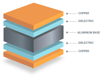
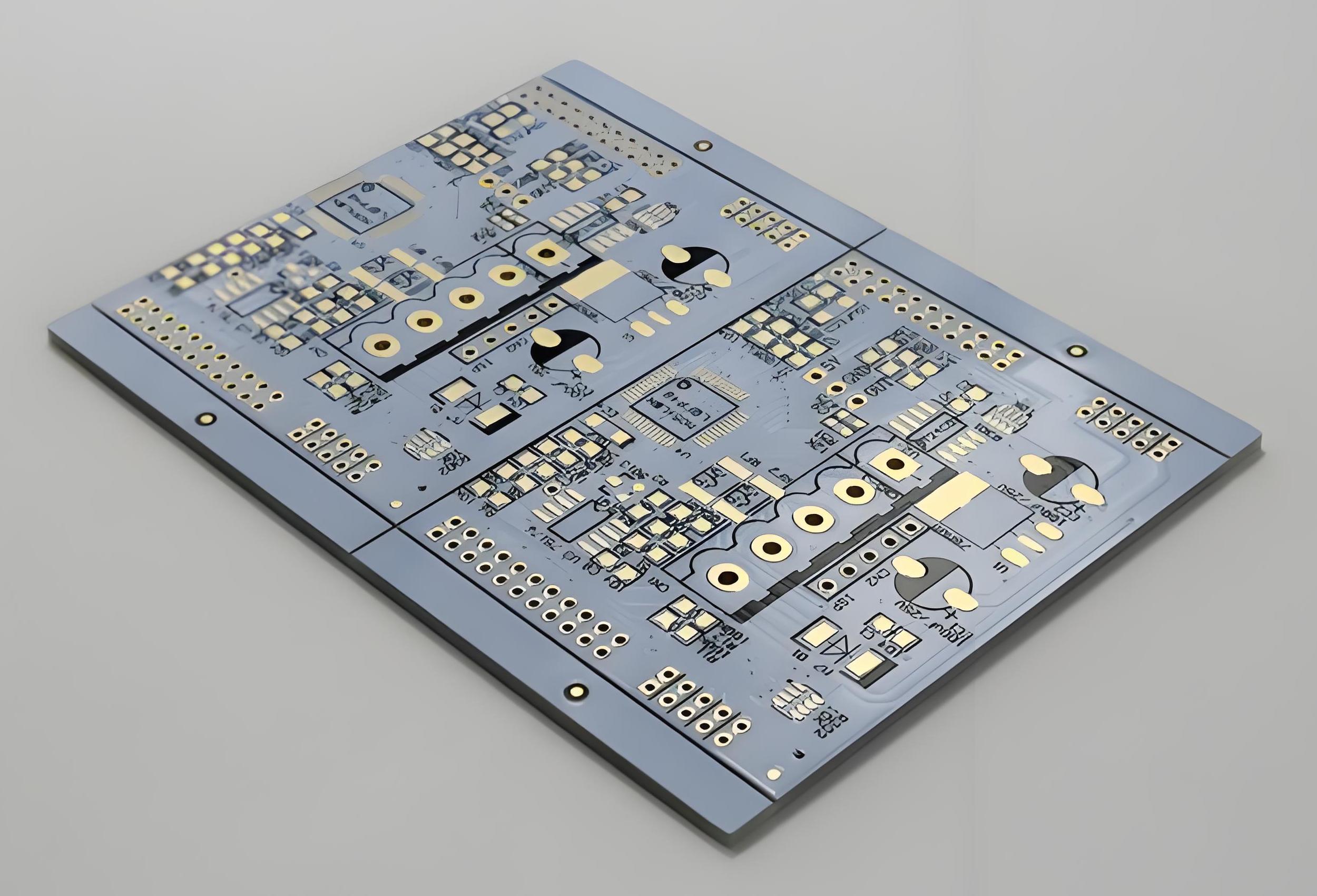
Aluminum PCBs consist of a metal base layer, typically aluminum, paired with a dielectric layer and copper circuitry. This construction provides superior thermal conductivity compared to traditional fiberglass substrates, making them ideal for applications where heat must be efficiently dissipated. For electric engineers, aluminum PCBs are crucial in high power and high frequency designs, as they prevent overheating and ensure signal integrity. Their ability to handle elevated temperatures directly impacts the lifespan and performance of electronic components.
These boards are particularly relevant in industries like automotive, aerospace, and telecommunications, where reliability under thermal stress is non-negotiable. By integrating aluminum PCBs into prototype designs, engineers can test and validate thermal management strategies early in the development cycle. Understanding their manufacturing process helps in aligning design requirements with production capabilities, ensuring a seamless transition from concept to finished product.
Technical Principles of Aluminum PCB Manufacturing
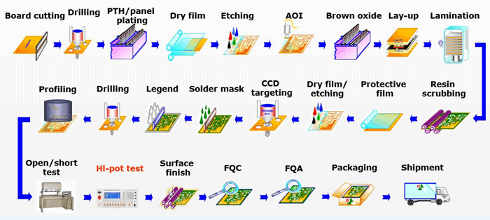
The manufacturing process of aluminum PCBs is distinct due to the metal core and the need for precise thermal and electrical insulation. Below, the key steps are outlined to provide electric engineers with a clear understanding of the technical principles involved.
Material Selection and Preparation
The process begins with selecting high quality aluminum as the base material, typically ranging in thickness based on thermal and structural needs. The aluminum layer acts as a heat sink, while a thin dielectric layer, often made of thermally conductive but electrically insulating material, is bonded to it. This layer ensures that electrical signals are isolated from the metal core. Copper foil is then applied for circuitry, with its thickness determined by current carrying requirements.
Layer Bonding and Lamination
Once materials are prepared, the dielectric layer is laminated onto the aluminum base under controlled heat and pressure. This step is critical to avoid air gaps, which can compromise thermal performance. The copper foil is bonded to the dielectric layer, forming the foundation for circuit patterns. Precision in lamination ensures consistent thermal conductivity across the board, a key factor for high frequency applications where signal stability is paramount.
Circuit Patterning and Etching
After lamination, the copper layer undergoes photolithography to define circuit patterns. A photoresist is applied, exposed to UV light through a mask, and developed to reveal the desired traces. Unwanted copper is etched away using chemical solutions, leaving behind the circuit layout. For aluminum PCBs, this process must account for the metal core’s properties to prevent damage to the underlying layers during etching.
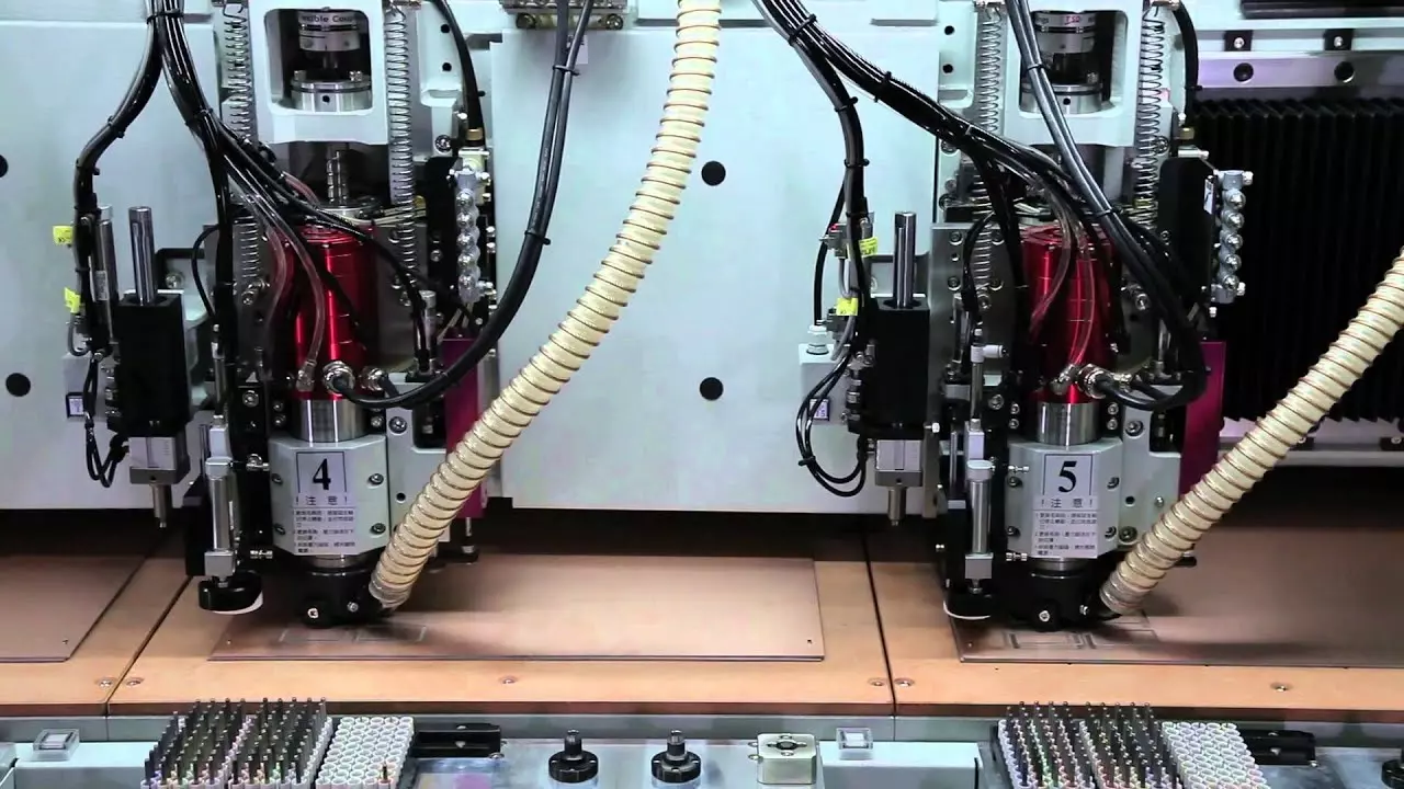
Drilling and Routing
Holes for vias and mounting are drilled with high precision to avoid stressing the metal core. Unlike standard PCBs, aluminum boards require specialized tools due to the hardness of the base material. Routing shapes the board to its final dimensions, ensuring edges are smooth to prevent mechanical stress points. These steps are vital for prototypes, as they impact the board’s fit and function in testing environments.
Surface Finishing and Insulation
Surface finishes like immersion silver or gold are applied to protect copper traces from oxidation and enhance solderability. An additional insulating layer, often a solder mask, is added to shield non contact areas. For high frequency designs, the choice of finish must minimize signal loss and impedance mismatches, aligning with specific design requirements.
Design Requirements for Aluminum PCBs in High Frequency Applications
Electric engineers working on high frequency circuits must consider specific design requirements when using aluminum PCBs. These boards are often chosen for their thermal benefits, but their electrical properties also play a critical role in signal performance. Below are key considerations to ensure optimal functionality.
Impedance Control
Maintaining consistent impedance is essential for high frequency signals to prevent reflections and signal degradation. The dielectric layer’s thickness and material properties directly influence impedance. Engineers must specify these parameters during the design phase, ensuring the manufacturing process aligns with calculated values. Tight control over trace width and spacing further supports impedance stability.
Thermal Management
High frequency circuits often generate significant heat due to rapid switching and power dissipation. Aluminum PCBs excel in transferring heat away from critical components, but design must incorporate thermal vias and heat sinks where necessary. Simulation tools can predict thermal behavior during prototype stages, allowing adjustments before full scale manufacturing.
Suggested Reading: Aluminum PCBs: Thermal Management for High Power Electronics
Signal Integrity
Signal integrity is a priority in high frequency PCB design. Minimizing crosstalk and electromagnetic interference requires careful layer stacking and grounding strategies. A solid ground plane near the aluminum core can act as a shield, reducing noise. Engineers should also avoid sharp bends in traces, as these can cause signal reflections.
Compliance with Standards
Adhering to industry standards ensures reliability and manufacturability. Guidelines such as IPC-6012E for rigid printed boards provide criteria for material selection, dimensional tolerances, and performance testing. Following these standards during design and manufacturing helps avoid issues in high frequency applications, ensuring the board meets operational demands.
Best Practices for Prototype Development with Aluminum PCBs
Developing prototypes with aluminum PCBs requires a strategic approach to balance cost, time, and performance. Electric engineers can follow these best practices to streamline the process and achieve reliable results.
Define Clear Design Objectives
Start by outlining the prototype’s purpose, whether it’s thermal testing, signal validation, or mechanical fit. Clear objectives guide material selection and manufacturing priorities. For high frequency prototypes, focus on dielectric properties and trace geometry to meet signal requirements.
Collaborate Early with Manufacturers
Engage with production teams during the design phase to understand manufacturing constraints. Aluminum PCBs have unique fabrication challenges, such as drilling through metal cores. Early collaboration ensures design requirements align with process capabilities, reducing iterations and delays in prototype development.
Iterate with Small Batches
Produce small batches of prototypes to test different design variations. This approach allows engineers to evaluate thermal performance, signal integrity, and mechanical stability without committing to large scale production. Feedback from each batch informs refinements for the final design.
Validate with Testing Standards
Use standardized testing methods to assess prototype performance. For instance, IPC-A-600K provides guidelines for visual inspection and acceptability criteria. Conducting thermal cycling and signal integrity tests ensures the aluminum PCB meets application specific needs before moving to full manufacturing.
Challenges in Aluminum PCB Manufacturing and Solutions
Manufacturing aluminum PCBs presents unique challenges due to the metal core and thermal requirements. Below are common issues and practical solutions for electric engineers to consider.
Warpage and Mechanical Stress
The difference in thermal expansion between aluminum, dielectric, and copper layers can cause warpage during manufacturing. To mitigate this, balanced layer stacking and controlled cooling after lamination are essential. Testing for flatness using standards like IPC-6012E ensures the board remains within acceptable limits.
Drilling Precision
Drilling through aluminum requires specialized equipment to avoid burrs and misalignment. Using carbide tools and optimized feed rates prevents damage to the core and dielectric. Regular tool maintenance and inspection further ensure precision, especially for high density designs.
Dielectric Layer Adhesion
Poor adhesion between the dielectric and aluminum can lead to delamination, compromising thermal performance. Surface treatment of the aluminum base before lamination enhances bonding. Manufacturers should also select dielectric materials with proven compatibility under thermal stress.
Conclusion
The aluminum PCB manufacturing process is a specialized sequence of steps tailored to deliver exceptional thermal management for demanding applications. For electric engineers, understanding this process is key to optimizing PCB design, especially in high frequency and prototype scenarios. From material selection to surface finishing, each stage requires attention to detail to meet stringent design requirements. By adhering to industry standards like IPC-6012E and focusing on best practices, engineers can ensure their aluminum PCBs perform reliably under challenging conditions. This knowledge empowers better decision making, from initial design to final production, ensuring successful outcomes in thermal and electrical performance.
FAQs
Q1: What are the key design requirements for aluminum PCBs in high frequency applications?
A1: For high frequency applications, aluminum PCB design must prioritize impedance control, signal integrity, and thermal management. Engineers should specify dielectric thickness and material to maintain consistent impedance. Ground planes near the metal core reduce noise, while thermal vias dissipate heat effectively. Adhering to standards like IPC-6012E ensures manufacturability and performance under high frequency conditions.
Q2: How does the manufacturing process of aluminum PCBs differ for prototypes?
A2: Aluminum PCB manufacturing for prototypes focuses on small batch production and flexibility to test design variations. The process includes precise material selection, careful lamination to avoid defects, and specialized drilling for the metal core. Early collaboration with manufacturers helps align prototype needs with production capabilities, ensuring quick iterations without compromising quality or thermal performance.
Q3: Why is thermal management critical in aluminum PCB design?
A3: Thermal management is vital in aluminum PCB design because it prevents component overheating, ensuring reliability in high power and high frequency circuits. The aluminum core efficiently conducts heat away from critical areas. Proper design, including thermal vias and heat sinks, enhances this capability, protecting performance and extending the lifespan of electronic systems under stress.
Q4: What standards should guide aluminum PCB manufacturing and design?
A4: Industry standards like IPC-6012E for rigid printed boards and IPC-A-600K for acceptability criteria are essential for aluminum PCB manufacturing and design. These provide guidelines on material selection, dimensional tolerances, and performance testing. Following such standards ensures consistent quality, reliability, and compatibility with high frequency and thermal requirements in engineering applications.
References
IPC-6012E — Qualification and Performance Specification for Rigid Printed Boards. IPC, 2020.
IPC-A-600K — Acceptability of Printed Boards. IPC, 2020.
ISO 9001:2015 — Quality Management Systems. ISO, 2015.