Introduction
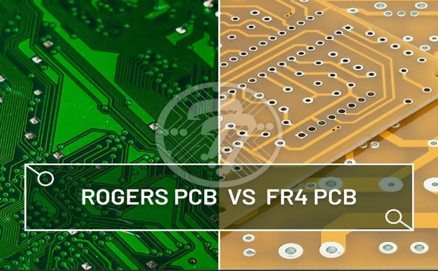
The relentless drive for faster data rates, higher operating frequencies, and more compact electronic designs has pushed the limits of traditional printed circuit board (PCB) materials. For decades, FR-4 has served as the backbone of the electronics industry due to its cost-effectiveness and reliable mechanical properties. However, its electrical limitations become pronounced in high-frequency applications, leading to signal integrity issues and performance degradation. As a result, the industry increasingly turns to specialized, advanced PCB laminates from manufacturers like Rogers Corporation. These materials are engineered to provide superior electrical performance, offering a robust foundation for next generation high-frequency circuits. This article delves into the critical need for moving beyond FR-4 and explores the characteristics of key Rogers PCB material comparison, such as RO4350B, RO4003C, and RT/duroid 5880, for demanding RF and microwave applications.
Why Standard FR-4 Falls Short for High-Frequency Laminates
FR-4, a glass-reinforced epoxy laminate, offers a good balance of electrical, mechanical, and thermal properties for general purpose PCBs. However, its inherent characteristics pose significant challenges when operating above a few gigahertz (GHz).
- Variable Dielectric Constant (Dk): The dielectric constant of FR-4 can vary significantly with frequency, temperature, and moisture absorption. This variability leads to unpredictable signal propagation speeds and impedance mismatches, which are detrimental to signal integrity in high-frequency designs.
- High Dissipation Factor (Df): FR-4 typically has a higher dissipation factor (or loss tangent) compared to specialized high-frequency laminates. A high Df means more energy is absorbed by the dielectric material as heat, leading to increased signal loss and reduced power efficiency, particularly in long transmission lines.
- Poor Dimensional Stability: FR-4's coefficient of thermal expansion (CTE) can be mismatched with copper, especially in the z-axis. This can lead to barrel cracking of plated through-holes and delamination during thermal cycling. While manageable at lower frequencies, it becomes more critical for high-density, multi-layer designs under elevated temperatures.
- Moisture Absorption: FR-4 materials can absorb moisture, which directly affects their Dk and Df. Changes in these electrical properties due to environmental humidity can alter circuit performance unpredictably.
These limitations make FR-4 unsuitable for applications requiring precise impedance control, minimal signal loss, and stable performance across wide temperature and frequency ranges, which are hallmarks of modern RF and microwave systems.
Understanding Key Electrical Properties of High-Frequency Laminates
Selecting the right high frequency laminate involves a deep understanding of several critical material properties that dictate electrical performance.
Dielectric Constant (Dk)
The dielectric constant, or relative permittivity (εr), measures a material's ability to store electrical energy in an electric field. For high-frequency applications, a consistent and stable Dk is paramount.
- Stability with Frequency: High-frequency laminates exhibit minimal change in Dk across a broad range of frequencies, ensuring predictable impedance control and signal propagation.
- Stability with Temperature: A stable Dk over temperature variations prevents signal phase shifts and impedance changes as the operating environment fluctuates.
- Consistency: Uniformity of Dk across the board surface and between production batches is vital for consistent manufacturing and circuit performance.
Dissipation Factor (Df)
The dissipation factor, also known as loss tangent (tan δ), quantifies the energy loss in a dielectric material.
- Low Df is Key: Lower Df values indicate less signal attenuation and power loss. This is crucial for maintaining signal amplitude, especially in applications with long traces or high power signals.
- Frequency Dependence: For high frequency laminate materials, Df should remain low and stable as frequency increases, preventing excessive heating and signal degradation.
Coefficient of Thermal Expansion (CTE)
CTE describes how much a material expands or contracts with changes in temperature.
- Z-Axis CTE: This is particularly important for multi-layer PCBs, as mismatched z-axis CTE between the laminate and copper plating can induce stress on plated through-holes, potentially leading to barrel cracks or delamination. Low and matched CTE to copper enhances reliability.
- X/Y-Axis CTE: While less critical than z-axis, a low x/y-axis CTE ensures dimensional stability of the PCB, which is important for precise component placement and alignment in dense designs.
Rogers Advanced PCB Materials: A Deep Dive
Rogers Corporation specializes in manufacturing advanced PCB laminates with tailored electrical, mechanical, and thermal properties. Here, we examine three prominent Rogers PCB material comparison options.
1. RO4003C™ Laminates
RO4003C is a ceramic-filled hydrocarbon resin system that provides an excellent balance of performance and processability, making it a popular alternative to FR-4 in many RF applications.
- Electrical Properties: It offers a stable Dk of 3.38 at 10 GHz and a low Df of 0.0027 at 10 GHz. These values are significantly better and more stable than FR-4.
- Thermal Properties: Its z-axis CTE is 44 ppm/°C, which is closer to copper's CTE (approximately 17 ppm/°C) than FR-4, improving plated through-hole reliability.
- Processability: RO4003C materials are designed to be processed using standard FR-4 manufacturing techniques, including drilling, desmear, and lamination, which can reduce manufacturing costs and complexity.
- Typical Applications: It is widely used in cellular base station antennas, power amplifiers, RF identification (RFID) tags, and automotive radar sensors.
2. RO4350B™ Laminates
RO4350B is another ceramic-filled hydrocarbon laminate, often considered for higher power and more demanding RF applications than RO4003C.
- Electrical Properties: It features a slightly higher Dk of 3.48 at 10 GHz, which allows for smaller circuit designs at a given frequency, and an ultra-low Df of 0.0037 at 10 GHz. Its Dk and Df are very stable over temperature and frequency.
- Thermal Properties: The z-axis CTE for RO4350B is 32 ppm/°C, providing even better plated through-hole reliability and dimensional stability than RO4003C. It also exhibits excellent thermal conductivity for improved heat dissipation.
- Processability: Similar to RO4003C, RO4350B is compatible with standard FR-4 processing, easing manufacturing integration.
- Typical Applications: Ideal for RF front-ends, power amplifiers, and high-frequency antenna arrays where power handling and stable performance across temperature are crucial.
3. RT/duroid® 5880 Laminates
RT/duroid 5880 is a polytetrafluoroethylene (PTFE) based composite, reinforced with glass microfiber. It represents the pinnacle of low-loss materials for extremely high-frequency and critical applications.
- Electrical Properties: It boasts an ultra-low Dk of 2.20 at 10 GHz, making it one of the lowest Dk values available, and an exceptionally low Df of 0.0009 at 10 GHz. These properties translate to minimal signal loss and phase distortion at millimeter-wave frequencies.
- Thermal Properties: Its z-axis CTE is excellent (108 ppm/°C), and it has very low moisture absorption, ensuring stable electrical performance in harsh environments.
- Processability: Due to its PTFE nature, RT/duroid 5880 requires specialized manufacturing processes for drilling, desmear, and etching, which can differ significantly from standard FR-4. This typically results in higher fabrication costs.
- Typical Applications: Suited for demanding applications such as aerospace radar systems, satellite communication, automotive collision avoidance systems (millimeter-wave radar), and high-frequency test equipment.
Rogers PCB Material Comparison Table
| Property / Material | FR-4 (Typical) | RO4003C | RO4350B | RT/duroid 5880 |
|---|---|---|---|---|
| Dk (at 10 GHz) | 4.2 – 4.7 | 3.38 | 3.48 | 2.20 |
| Df (at 10 GHz) | 0.018 – 0.025 | 0.0027 | 0.0037 | 0.0009 |
| Z-Axis CTE (ppm/°C) | 50 – 70 | 44 | 32 | 108 |
| Moisture Absorption (%) | 0.1 – 0.2 | 0.06 | 0.06 | 0.02 |
| Processing | Standard | FR-4 Like | FR-4 Like | Specialized |
| Cost (Relative) | Low | Medium | Medium | High |
| Thermal Conductivity (W/m/K) | 0.25 | 0.64 | 0.69 | 0.25 |
Note: Dk and Df values are typical and can vary slightly based on specific laminate thickness and test methods. Values for RT/duroid 5880 are also very stable at even higher frequencies, typically up to 40 GHz and beyond.
Manufacturing Considerations for Rogers Laminates
While RO4003C and RO4350B are generally compatible with FR-4 processing, some nuances are important for optimal yield and performance.
- Drilling: Optimal drill bit speeds and feeds, along with proper entry and exit materials, are crucial to minimize burring and ensure clean holes.
- Desmear and Plating: Specialized plasma desmear cycles might be required for RT/duroid 5880 to ensure good adhesion of electroless copper plating to the PTFE material. Plating bath chemistries and parameters must be carefully controlled.
- Lamination: For multi-layer constructions involving hybrid stack-ups (e.g., Rogers materials with FR-4), lamination cycles need precise control of temperature, pressure, and time to prevent delamination or resin starvation. IPC-6012E, Qualification and Performance Specification for Rigid Printed Boards, provides general guidelines for rigid PCB manufacturing.
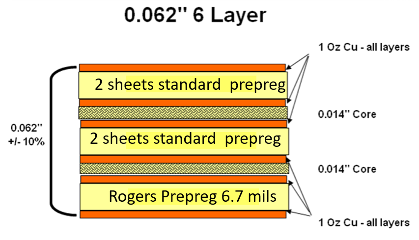
Hybrid Stack-ups: Combining Performance and Cost-Effectiveness
For many complex applications, a pure Rogers PCB material comparison against FR-4 might not be the most cost-effective solution. Hybrid stack-ups combine layers of high-frequency laminates (e.g., RO4003C or RO4350B) for critical RF sections with less expensive FR-4 for non-critical digital or power layers. This approach allows designers to achieve localized high-frequency performance where needed, while controlling overall manufacturing costs. The successful fabrication of hybrid stack-ups requires careful design and precise control during the lamination process to manage potential CTE mismatches.
Conclusion
The transition from FR-4 to advanced PCB laminates like those offered by Rogers Corporation is indispensable for the successful development and manufacturing of high-frequency electronic systems. Materials such as RO4003C, RO4350B, and RT/duroid 5880 provide superior and stable electrical properties—specifically Dk and Df—that are critical for signal integrity, minimal loss, and reliable operation at high frequencies. By carefully evaluating the specific electrical, thermal, and mechanical requirements of an application and understanding the manufacturing implications, engineers can select the most appropriate high frequency laminate to optimize performance, enhance reliability, and ensure the manufacturability of cutting edge electronic devices. This strategic material selection is a cornerstone of robust high-frequency PCB manufacturing.
FAQs
Q1: Why is FR-4 generally not suitable for high-frequency applications compared to Rogers PCB materials?
A1: FR-4 is unsuitable for high-frequency applications due to its variable dielectric constant (Dk) and high dissipation factor (Df) which fluctuate with frequency and temperature. This leads to signal loss, impedance mismatches, and unpredictable performance, unlike specialized high frequency laminate materials from Rogers.
Q2: What are the main advantages of RO4350B laminates for RF applications?
A2: RO4350B laminates offer excellent advantages for RF applications with their stable Dk of 3.48 and low Df of 0.0037 at 10 GHz. Its lower z-axis CTE and good thermal conductivity enhance plated through-hole reliability and heat dissipation, making it ideal for power amplifiers and RF front ends.
Q3: When should RT/duroid 5880 be considered over other advanced PCB laminates?
A3: RT/duroid 5880 should be considered for extremely high-frequency (millimeter-wave) and mission critical applications where ultra-low Dk (2.20 at 10 GHz) and Df (0.0009 at 10 GHz) are paramount. Its superior electrical stability and minimal loss are crucial despite requiring specialized manufacturing processes.
Q4: What are hybrid stack-ups in the context of Rogers PCB materials?
A4: Hybrid stack-ups combine advanced PCB laminates like RO4003C or RO4350B for critical high-frequency layers with more cost-effective FR-4 for non-critical layers. This approach optimizes performance where necessary while managing overall manufacturing costs and is a common practice in modern PCB manufacturing.
References
IPC-2221A — Generic Standard on Printed Board Design. IPC, 2003.
IPC-2222B — Sectional Design Standard for Rigid Organic Printed Boards. IPC, 2010.
IPC-6012E — Qualification and Performance Specification for Rigid Printed Boards. IPC, 2017.