Introduction
In the realm of printed circuit board design, material selection plays a pivotal role in determining performance, reliability, and suitability for specific applications. While FR-4 has long been the standard choice for many electrical engineers due to its cost-effectiveness and versatility, it often falls short in high-frequency, high-speed, or thermally challenging environments. This is where Rogers PCBs application becomes critical. These advanced laminates offer superior electrical and thermal properties, making them a preferred option over FR-4 in demanding scenarios. This article explores the distinct Rogers PCBs advantage, compares FR-4 and Rogers PCBs, and guides engineers on where to use Rogers PCBs for optimal results. Tailored for electrical engineers, the discussion focuses on technical merits and practical considerations for integrating these materials into cutting-edge designs.
What Are Rogers PCBs and Why Do They Matter?
Rogers PCBs refer to circuit boards made from specialized high-performance laminates developed for applications requiring exceptional electrical properties. Unlike FR-4, which is a glass-reinforced epoxy laminate, Rogers materials are often based on hydrocarbon or ceramic-filled compositions. These laminates are engineered to provide low dielectric loss, stable dielectric constants, and excellent thermal management, addressing limitations seen in FR-4 and Rogers PCBs comparisons.
The importance of Rogers PCBs lies in their ability to support modern technologies. As industries push toward faster data rates, higher frequencies, and compact designs, the need for materials that minimize signal loss and maintain integrity under stress grows. Applications such as 5G telecommunications, aerospace systems, and automotive radar rely on the Rogers PCBs advantage to ensure performance. For electrical engineers, understanding these materials opens pathways to designing reliable circuits for environments where standard FR-4 cannot compete.
Technical Principles of Rogers PCBs Over FR-4
To appreciate where to use Rogers PCBs, engineers must grasp the fundamental differences in material properties compared to FR-4. The primary technical advantages center on dielectric performance, thermal stability, and mechanical characteristics.
First, dielectric properties define signal integrity in high-frequency designs. FR-4 typically exhibits a dielectric constant around 4.2 to 4.5, with a relatively high dissipation factor, leading to signal loss at frequencies above a few gigahertz. In contrast, Rogers laminates offer dielectric constants as low as 2.2 and dissipation factors significantly below those of FR-4. This results in reduced signal attenuation, making Rogers PCBs ideal for RF and microwave applications.
Thermal stability is another critical area. FR-4 has a glass transition temperature around 130 to 140 degrees Celsius, limiting its use in high-heat environments. Rogers materials often withstand higher temperatures, with some variants stable beyond 200 degrees Celsius, alongside better thermal conductivity. This ensures reliability in power electronics and harsh conditions.
Mechanically, Rogers laminates provide consistent dimensional stability, reducing issues like warping during thermal cycling. FR-4 can absorb moisture, affecting electrical performance, while Rogers materials show minimal water absorption, preserving integrity in humid settings. These factors collectively highlight why Rogers PCBs over FR-4 are chosen for demanding projects.
Key Advantages of Rogers PCBs for Electrical Engineers
- Superior High-Frequency Performance: With low dielectric loss, Rogers PCBs maintain signal clarity at frequencies where FR-4 fails. This is vital for RF circuits, antennas, and high-speed digital systems.
- Enhanced Thermal Management: Higher thermal conductivity and stability allow Rogers PCBs to dissipate heat effectively, reducing the risk of component failure in power-intensive designs.
- Stable Electrical Properties: A consistent dielectric constant across a wide frequency range ensures predictable behavior, critical for precision applications like radar and telecommunications.
- Reduced Signal Loss: Lower dissipation factors minimize energy loss, supporting efficient signal transmission over long traces or at high data rates.
- Durability in Harsh Environments: Resistance to moisture and temperature fluctuations makes Rogers PCBs suitable for aerospace and automotive sectors.
These advantages position Rogers PCBs over FR-4 as the material of choice when performance cannot be compromised. Electrical engineers can leverage these properties to meet stringent design requirements without sacrificing reliability.
Practical Applications of Rogers PCBs
Understanding Rogers PCBs application areas helps engineers decide where to integrate these materials. Their unique properties cater to industries and systems with specific demands beyond FR-4 capabilities.
- Telecommunications: In 5G infrastructure, base stations, and satellite communications, Rogers PCBs support high-frequency signals with minimal loss, ensuring data integrity over vast networks.
- Aerospace and Defense: Radar systems, avionics, and military communications require materials that handle extreme conditions. Rogers PCBs provide the necessary thermal and electrical stability.
- Automotive Electronics: Advanced driver-assistance systems and vehicle-to-everything communication rely on high-speed, reliable circuits. Rogers materials meet these needs under varying environmental stresses.
- Medical Devices: High-frequency imaging equipment and wearable sensors benefit from the precision and low noise offered by Rogers laminates.
- Industrial Systems: Power amplifiers and high-speed industrial controls use Rogers PCBs to manage heat and maintain performance in rugged settings.
For engineers, identifying where to use Rogers PCBs involves assessing frequency requirements, thermal loads, and environmental factors. These applications demonstrate how Rogers PCBs over FR-4 deliver measurable improvements in critical systems.
Comparing FR-4 and Rogers PCBs: When to Choose Which?
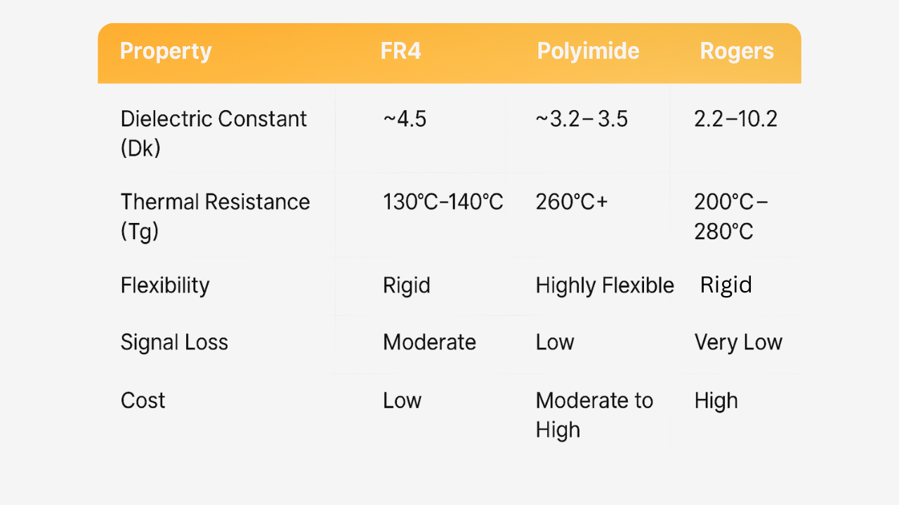
Selecting between FR-4 and Rogers PCBs requires a balanced evaluation of project needs, performance goals, and budget constraints. Below is a comparison to guide decision-making.
- Dielectric Constant: FR-4 = 4.2 to 4.5; Rogers PCBs = 2.2 to 3.5 (varies by type).
- Dissipation Factor: Higher (more signal loss) for FR-4; Lower (better signal integrity) for Rogers PCBs.
- Thermal Stability: Limited (Tg ~130-140°C) for FR-4; Higher (often >200°C) for Rogers PCBs.
- Cost: Lower for FR-4; Higher for Rogers PCBs.
- Best Use Cases: FR-4 for general-purpose, low-frequency; Rogers PCBs for high-frequency, high-heat.
FR-4 remains suitable for cost-sensitive, less demanding projects where frequencies stay below a few gigahertz, and thermal stress is minimal. Examples include consumer electronics and basic control boards. However, when designs involve RF signals, high data rates, or extreme conditions, the Rogers PCBs advantage becomes indispensable. Engineers should prioritize Rogers materials for applications outlined earlier, ensuring compliance with performance standards like those in IPC-6012E for rigid printed boards.
Best Practices for Designing with Rogers PCBs
To maximize the benefits of Rogers PCBs, electrical engineers must follow specific design and manufacturing guidelines. These practices ensure optimal performance while adhering to industry standards.
First, consider material selection early in the design phase. Different Rogers laminates suit specific frequency ranges and thermal needs. Consulting dielectric and thermal conductivity data ensures the chosen material aligns with project goals.
Second, account for tighter tolerances in layout design. High-frequency applications demand precise impedance control. Use simulation tools to model signal behavior and minimize reflections or crosstalk, following guidelines from standards like IPC-A-600K for acceptability criteria.
Third, optimize stack-up configurations. Rogers materials often pair with other laminates in hybrid designs to balance cost and performance. Ensure proper bonding and layer alignment to prevent delamination during fabrication.
Finally, collaborate with fabrication teams to verify process compatibility. Rogers laminates may require adjusted drilling or lamination parameters compared to FR-4. Adhering to IPC-6012E specifications helps maintain board quality during production.
Conclusion
For electrical engineers tackling demanding applications, moving beyond FR-4 to embrace Rogers PCBs offers transformative potential. The Rogers PCBs advantage lies in superior high-frequency performance, thermal stability, and reliability under stress, making them indispensable for technologies like 5G, aerospace systems, and automotive electronics. By understanding where to use Rogers PCBs and leveraging their strengths over FR-4, engineers can design circuits that meet the rigorous demands of modern industries. Comparing FR-4 and Rogers PCBs reveals clear use cases for each, guiding informed material choices. With careful design practices and adherence to industry standards, Rogers PCBs unlock new possibilities for innovation and performance in challenging environments.
FAQs
Q1: What are the primary Rogers PCBs application areas for electrical engineers?
A1: Rogers PCBs application focuses on high-frequency and high-performance scenarios like 5G telecommunications, aerospace radar, automotive systems, and medical imaging. These materials excel in environments requiring low signal loss and thermal stability, unlike standard FR-4. Engineers choose them for designs where precision and reliability under stress are non-negotiable, ensuring optimal circuit performance.
Q2: How does the Rogers PCBs advantage impact high-speed designs?
A2: The Rogers PCBs advantage in high-speed designs includes low dielectric loss and stable electrical properties. This minimizes signal attenuation and ensures consistent performance at high frequencies. Compared to FR-4, Rogers materials reduce noise and improve data integrity, making them ideal for applications like high-speed digital systems and RF circuits where timing and clarity are critical.
Q3: Where to use Rogers PCBs instead of FR-4 for optimal results?
A3: Knowing where to use Rogers PCBs is key for projects involving frequencies above a few gigahertz, extreme temperatures, or harsh environments. Applications in telecommunications, defense, and automotive electronics benefit most. If signal integrity and thermal management are priorities over cost, Rogers materials outperform FR-4, ensuring reliability in demanding conditions.
Q4: What design challenges arise when using Rogers PCBs over FR-4?
A4: Using Rogers PCBs over FR-4 introduces challenges like higher material costs and the need for precise impedance control. Engineers must account for tighter tolerances in layout and ensure fabrication processes align with the material’s properties. Following industry standards for design and manufacturing helps mitigate risks and achieve consistent performance in high-frequency applications.
IPC-6012E — Qualification and Performance Specification for Rigid Printed Boards. IPC, 2020.
IPC-A-600K — Acceptability of Printed Boards. IPC, 2020.