Introduction
The escalating demands of modern electronics, particularly in high-frequency applications like 5G communication, radar systems, and high-power modules, have pushed the boundaries of traditional printed circuit board (PCB) materials. For decades, FR-4 has been the ubiquitous choice due to its balance of cost, mechanical properties, and ease of processing. However, its inherent electrical and thermal limitations become significant hurdles as operating frequencies extend into the gigahertz range and power densities increase. This critical need for enhanced performance has led to the adoption of specialized substrates, with ceramic PCB technology emerging as a robust alternative. Understanding the fundamental differences in a PCB material comparison between ceramic PCB vs FR-4 is essential for designers to select the optimal material for their high-frequency designs, ensuring both performance and reliability.
FR-4: The Standard and Its High-Frequency Limitations
FR-4 is a composite material made of woven fiberglass cloth with an epoxy resin binder. It is widely used for general purpose PCBs due to its:
- Cost-Effectiveness: Relatively inexpensive to manufacture.
- Good Mechanical Strength: Provides a stable platform for components.
- Ease of Processing: Compatible with standard PCB manufacturing techniques.
However, for high-frequency PCB materials, FR-4 presents several critical limitations:
- Variable Dielectric Constant (Dk) and High Dissipation Factor (Df): The Dk of FR-4 varies significantly with frequency, temperature, and moisture content. Its Df (loss tangent) is also relatively high, leading to substantial signal loss (attenuation) at higher frequencies (typically above 1-2 GHz). This compromises signal integrity and power efficiency.
- Poor Thermal Conductivity: FR-4 has a low thermal conductivity comparison (typically around 0.25 W/m·K). This limits its ability to dissipate heat efficiently, leading to localized hot spots and potential component degradation in high-power applications.
- Higher Coefficient of Thermal Expansion (CTE): FR-4's CTE, particularly in the z-axis, is often mismatched with copper. This can induce stress on plated through-holes and solder joints during thermal cycling, leading to reliability issues.
- Moisture Absorption: FR-4 can absorb moisture, which further degrades its electrical properties, especially Dk and Df, making performance unpredictable in humid environments.
These limitations make FR-4 a suboptimal choice for designs where precise impedance control, minimal signal loss, and robust thermal management are paramount.
Related Reading: Exploring the World of Multilayer FR-4 PCBs: Design, Manufacturing, and Applications
Ceramic PCB: A High-Performance Alternative
A ceramic PCB utilizes a ceramic material as its substrate, typically alumina (Al2O3) or aluminum nitride (AlN). These materials offer a dramatically different set of properties, making them ideal high-frequency PCB materials.
- Alumina (Al2O3) PCB: The most common type, offering excellent electrical insulation and good thermal conductivity.
- Aluminum Nitride (AlN) PCB: Provides even higher thermal conductivity, making it suitable for extremely high-power applications.
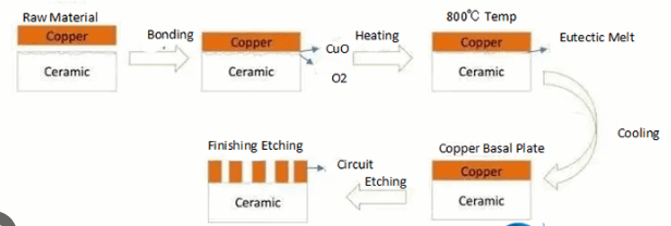
Ceramic PCBs are manufactured using various techniques, including thick film, thin film, and direct bonded copper (DBC).
Key Advantages of Ceramic PCBs:
- Superior High-Frequency Performance: Ceramic materials exhibit extremely stable Dk and very low Df across a wide range of frequencies (up to hundreds of GHz) and temperatures. This ensures excellent signal integrity, minimal signal loss, and predictable impedance control.
- Exceptional Thermal Conductivity: Ceramic substrates, especially AlN, offer significantly higher thermal conductivity comparison than FR-4 (Alumina ~20-30 W/m·K, AlN ~170-220 W/m·K). This enables highly efficient heat dissipation directly through the substrate, reducing hot spots and eliminating the need for bulky external heat sinks in many cases.
- Excellent Dimensional Stability: Ceramic materials have very low CTEs that closely match those of silicon chips (e.g., Al2O3 ~7 ppm/°C, AlN ~4.7 ppm/°C, Si ~2.6 ppm/°C). This minimizes thermal stress on soldered components, improving reliability, especially for direct die attach (chip-on-board) and wire bonding applications.
- High Temperature Resistance: Ceramic PCBs can withstand much higher operating temperatures than FR-4 without degradation, making them suitable for extreme environments.
- Hermetic Sealing Capability: The dense, non-porous nature of ceramic allows for hermetic packaging, protecting sensitive circuits from moisture and contaminants.
- Chemical Resistance: Ceramic materials are highly resistant to most chemicals, offering durability in harsh industrial settings.
Ceramic PCB vs FR-4: A Detailed Material Comparison
Let's delve into a direct PCB material comparison between ceramic PCB vs FR-4 across critical parameters.
1. Electrical Performance
- FR-4: Dk typically 4.2-4.7 (variable), Df typically 0.018-0.025 (high and frequency-dependent).
- Ceramic PCB: Dk typically 2.2-10 (stable, depending on type), Df typically 0.0001-0.003 (very low and stable).
- Impact: Ceramic offers significantly lower signal loss, more stable impedance, and better signal integrity for high-frequency PCB materials.
2. Thermal Conductivity
- FR-4: Low (approx. 0.25 W/m·K).
- Ceramic PCB: High (Alumina 20-30 W/m·K, AlN 170-220 W/m·K).
- Impact: Ceramic PCBs are vastly superior for thermal conductivity comparison, enabling direct heat dissipation from components and reducing system operating temperatures. This is critical for power electronics and high-power RF modules.
3. Mechanical Properties
- FR-4: Good flexural strength, moderate hardness, relatively lightweight.
- Ceramic PCB: Very high hardness, brittle, excellent dimensional stability, denser than FR-4.
- Impact: Ceramic provides a very stable substrate, ideal for direct die attach, but is brittle and requires careful handling. FR-4 is more robust against mechanical shock but less dimensionally stable.
4. Coefficient of Thermal Expansion (CTE)
- FR-4: Z-axis CTE typically 50-70 ppm/°C (high and mismatched with copper/silicon).
- Ceramic PCB: Low and closely matched to silicon (Alumina ~7 ppm/°C, AlN ~4.7 ppm/°C).
- Impact: Ceramic minimizes thermal stress on components and solder joints, especially crucial for bare die applications and wire bonding, improving long term reliability.
5. Cost
- FR-4: Low cost of ceramic PCB in comparison, mass-produced.
- Ceramic PCB: High cost of ceramic PCB due to raw materials, specialized processing, and lower production volumes.
- Impact: Ceramic PCBs are a premium solution, justified only when performance requirements cannot be met by FR-4 or advanced organic laminates.
6. Manufacturing Process
- FR-4: Standard PCB fabrication processes, widely accessible.
- Ceramic PCB: Requires specialized equipment and processes (e.g., laser drilling, advanced etching, high-temperature firing), resulting in fewer specialized manufacturers.
- Impact: Lead times and fabrication options for ceramic PCBs can be more limited compared to FR-4.
Related Reading: Thermal Management Secrets: Optimizing Heat Dissipation with Ceramic PCBs
Applications Where Each Material Excels
The choice between ceramic PCB vs FR-4 often comes down to the specific application's demands.
When to Choose FR-4:
- General purpose electronics (consumer, industrial control, some computing).
- Low-cost applications where high-frequency performance or extreme thermal management is not critical.
- Prototypes or designs with flexible iteration requirements.
- Applications operating below 1-2 GHz where signal loss is tolerable.
When to Choose Ceramic PCB:
- High-Frequency RF and Microwave Circuits: Power amplifiers, filters, antennas, radar modules, 5G base stations.
- High-Power Electronics: LED lighting (especially high-brightness), automotive power control, industrial power modules, where efficient thermal conductivity comparison is essential.
- Medical Implants and Devices: Biocompatibility and hermetic sealing capabilities.
- Harsh Environment Electronics: High temperature, chemically aggressive environments.
- Optoelectronics: Laser diodes, optical sensors, where precise thermal management and dimensional stability are needed.
- Direct Die Attach (Chip-on-Board) Applications: Where the CTE match with silicon is crucial for reliability.
Conclusion
The decision between utilizing ceramic PCB vs FR-4 is pivotal for the success of high-frequency and high-power electronic designs. While FR-4 remains the cost-effective workhorse for general electronics, its electrical losses and poor thermal performance at higher frequencies make it unsuitable for modern demanding applications. Ceramic PCB materials, with their superior thermal conductivity, stable electrical properties (low Dk and Df), and excellent dimensional stability, provide the high-performance foundation required for critical RF, microwave, and power electronics. Although the cost of ceramic PCB is significantly higher and its manufacturing more specialized, the long-term benefits in terms of reliability, efficiency, and uncompromised performance often justify the investment. Designers must perform a thorough PCB material comparison, weighing the technical requirements against budget and manufacturing considerations to choose the right material that optimizes their specific high-frequency design.
FAQs
Q1: What are the main limitations of FR-4 as a high-frequency PCB material?
A1: The main limitations of FR-4 as a high-frequency PCB material are its variable dielectric constant (Dk), high dissipation factor (Df) leading to signal loss, poor thermal conductivity, and a CTE mismatch with copper, all of which degrade performance and reliability at high frequencies.
Q2: How does the thermal performance of ceramic PCBs compare to FR-4?
A2: The thermal conductivity comparison shows ceramic PCBs are vastly superior to FR-4. Ceramic materials like alumina and aluminum nitride offer thermal conductivities orders of magnitude higher (e.g., AlN up to 220 W/m·K vs. FR-4's 0.25 W/m·K), enabling efficient heat dissipation and cooler operating temperatures.
Q3: What factors contribute to the higher cost of ceramic PCBs compared to FR-4?
A3: The higher cost of ceramic PCB is primarily due to the expense of raw ceramic materials, specialized and more complex PCB manufacturing processes (like high-temperature firing and laser drilling), and lower production volumes compared to the mass-produced FR-4.
Q4: In which applications are ceramic PCBs typically preferred over FR-4?
A4: Ceramic PCBs are typically preferred over FR-4 in applications requiring high-frequency PCB materials such as RF and microwave circuits, high-power electronics, medical implants, and harsh environment electronics, where stable electrical properties, superior thermal management, and high reliability are critical.
References
IPC-2221A — Generic Standard on Printed Board Design. IPC, 2003.
IPC-2222B — Sectional Design Standard for Rigid Organic Printed Boards. IPC, 2010.
IPC-6012E — Qualification and Performance Specification for Rigid Printed Boards. IPC, 2017.