Introduction
The rapid evolution of wireless communication, radar systems, and high-speed data transfer has placed increasing demands on printed circuit board (PCB) design and manufacturing. Central to achieving reliable performance in these applications is the meticulous selection of components suitable for high-frequency operation. Unlike conventional low-frequency circuits, high-frequency PCBs require components that maintain their electrical characteristics across broad bandwidths, minimize parasitic effects, and withstand the rigors of modern manufacturing processes. This comprehensive overview explores the critical considerations and best practices for component selection in high-frequency PCB manufacturing, ensuring optimal signal integrity and system reliability.
Why High-Frequency Component Selection Matters
In high-frequency circuits, the physical dimensions of components, traces, and dielectric materials become comparable to the signal's wavelength. At these frequencies, parasitic inductance and capacitance, which are negligible at lower frequencies, significantly impact circuit performance. Improper component selection can lead to:
- Signal Integrity Degradation: Increased reflections, impedance mismatches, and crosstalk.
- Reduced Bandwidth: Limitations on the circuit's operating frequency range.
- Increased Power Loss: Higher insertion loss and dissipated energy as heat.
- Unwanted Oscillations: Instabilities due to parasitic feedback loops.
- Electromagnetic Interference (EMI): Unintentional radiation or susceptibility.
Therefore, selecting components specifically designed and characterized for high-frequency applications is paramount to achieving the desired electrical performance and manufacturing yield.
Key Considerations for High-Frequency Component Selection
Several factors become critically important when choosing components for high-frequency PCBs, ranging from material properties to packaging styles.
1. Material Properties of Components
The internal materials and construction of components greatly influence their high-frequency behavior.
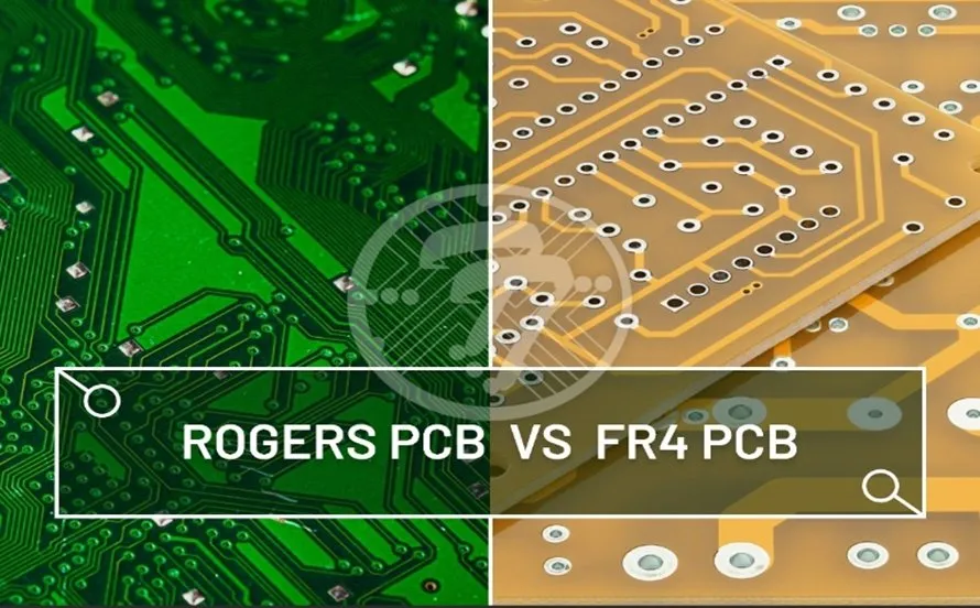
- Dielectric Materials: For capacitors, the dielectric material (e.g., C0G/NP0 ceramic for high stability, X7R for higher capacitance with some temperature dependency) dictates stability, loss tangent, and frequency response.
- Conductor Materials: Internal lead frames and terminations should have good conductivity and low skin effect at high frequencies.
- Magnetic Materials: For inductors, the core material must maintain high permeability and low loss at the operating frequency.
2. Parasitic Effects
Understanding and minimizing parasitic effects is central to high-frequency component selection.
- Equivalent Series Resistance (ESR): A significant factor for capacitors and inductors, representing the resistive losses at high frequencies. Low ESR is crucial for filter performance and power efficiency.
- Equivalent Series Inductance (ESL): The intrinsic inductance of a capacitor, which can cause it to self-resonate and become inductive at higher frequencies.
- Equivalent Parallel Capacitance (EPC): The intrinsic capacitance of an inductor, causing it to self-resonate and become capacitive.
These parasitic elements fundamentally limit a component's useful frequency range.
3. Packaging and Form Factor
The physical package of a component plays a critical role in its high-frequency performance and manufacturability.
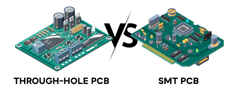
- Surface Mount Device (SMD) Components: SMD components are almost universally preferred for high-frequency PCBs due to their smaller size, lower parasitic inductance and capacitance compared to through-hole components, and suitability for automated assembly (SMT assembly). Their compact footprint also allows for denser designs.
- Lead Length and Design: Shorter leads and direct solder connections of SMDs minimize parasitic inductance. Leadless packages like QFNs (Quad Flat No-leads) or BGAs (Ball Grid Arrays) often offer superior high-frequency performance.
- Thermal Considerations: Packaging must also effectively dissipate heat, especially for power RF components.
Specific High-Frequency Component Types
A detailed look at the selection criteria for key RF components is essential for high-frequency PCB design.
A. High-Frequency Capacitors
High-frequency capacitors are crucial for filtering, bypassing, and resonant circuits.
- Low ESR and ESL: These are primary selection criteria. Capacitors with low ESR minimize power loss and heat generation, while low ESL ensures effective decoupling and filtering at higher frequencies.
- Dielectric Type: C0G/NP0 ceramic capacitors are favored for high-frequency resonant circuits and timing applications due to their excellent temperature stability and low dielectric loss (high Q factor). X7R and X5R are suitable for decoupling in power delivery networks but have higher loss and temperature dependency.
- Self-Resonant Frequency (SRF): Capacitors become inductive above their SRF. For effective decoupling, the SRF should be well above the operating frequency or target harmonics.
- Voltage Rating: Must accommodate peak voltages, considering ripple and transient conditions.
B. High-Frequency Inductors
High-frequency inductors are used in filters, matching networks, and DC-DC converters.
- High Q Factor: The quality factor (Q) indicates the efficiency of an inductor. A higher Q factor means lower losses and sharper filter response. Q factor typically degrades at higher frequencies.
- Self-Resonant Frequency (SRF): Similar to capacitors, inductors become capacitive above their SRF. The SRF must be significantly higher than the operating frequency.
- Current Handling: Must support the peak current without saturating the core or overheating.
- Core Material: Air core inductors (or non-magnetic core) are often used for very high frequencies to avoid core losses and saturation. Ferrite cores are common for lower RF frequencies but require careful selection to match the operating frequency range.
- Tolerance: Tight tolerance inductors are required for precise filter or matching network designs.
C. RF Connectors
RF connectors are external components, but their selection directly impacts the PCB's high-frequency performance.
- Impedance Matching: Connectors must maintain a consistent characteristic impedance (typically 50 ohms or 75 ohms) to match the transmission lines on the PCB and connected cables. Mismatches cause reflections and signal loss.
- Low Insertion Loss and Return Loss: These parameters quantify the signal attenuation through the connector and the amount of signal reflected, respectively. High-quality connectors exhibit low insertion loss and high return loss across the operating frequency band.
- Shielding Effectiveness: Good shielding is vital to prevent EMI leakage or ingress.
- Mechanical Durability: Connectors must withstand repeated mating cycles without degrading electrical performance. Common RF components for PCB mounting include SMA, U.FL, and SMP connectors.
D. Other Key RF Components
- Resistors: While seemingly simple, high-frequency resistors should have low parasitic inductance and capacitance. Chip resistors are generally preferred over wirewound or carbon composition types.
- Diodes and Transistors: RF components like diodes (e.g., PIN diodes for switching, Schottky diodes for mixing) and RF transistors (e.g., GaAs, GaN, SiGe HBTs) require specific characterization for gain, noise figure, and linearity at target frequencies. Packaging (e.g., leadless DFN, QFN) is critical for minimizing parasitics.
- Filters and Attenuators: These are often integrated passive components (IPD) or discrete circuits built from precisely selected capacitors and inductors. Integrated solutions often offer better performance and smaller size.
Manufacturing Considerations in Component Selection
Beyond electrical performance, manufacturability is a crucial aspect of component selection, particularly for SMD components.
- Solderability: Component terminations must have good solderability to ensure reliable solder joints during reflow or wave soldering. This is governed by standards such as J-STD-002E, Solderability Tests for Components.
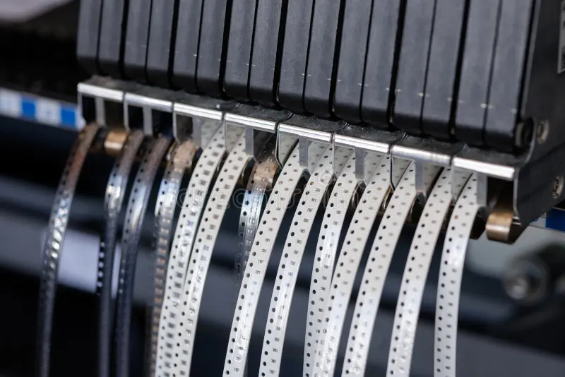
- Pick and Place Compatibility: SMD components must be compatible with automated pick and place machines, typically supplied in tape and reel packaging for efficient manufacturing.
- Moisture Sensitivity Level (MSL): Moisture sensitive components (per JEDEC J-STD-020E, Moisture/Reflow Sensitivity Classification) require specific handling and storage to prevent damage during reflow.
- Thermal Budget: The maximum allowable temperature for a component during soldering must be respected, especially with sensitive RF components.
Thermal Management in Component Selection
Thermal management is an integral part of high-frequency component selection. Many RF components, particularly power amplifiers and high-speed processors, generate significant heat.
- Power Dissipation: Designers must select components with adequate power dissipation capabilities for the application.
- Thermal Pads: Components often feature exposed thermal pads underneath the package for direct heat transfer to the PCB ground plane or thermal vias. The PCB design must incorporate matching thermal pads and vias for effective heat sinking.
- Operating Temperature Range: Components must reliably operate within the specified ambient and junction temperature ranges.
Conclusion
Effective component selection for high-frequency PCBs is a nuanced process that demands a deep understanding of electrical physics, material science, and manufacturing constraints. By prioritizing SMD components with low parasitic effects, selecting high-frequency capacitors and inductors with optimized Q factors and SRFs, and choosing RF connectors that maintain impedance and minimize loss, designers can lay the foundation for a high-performance circuit. Adherence to industry standards and careful consideration of thermal and manufacturability aspects are equally vital, ensuring that the final manufactured PCB not only meets rigorous performance specifications but also achieves robust reliability and consistent quality.
FAQs
Q1: What are the primary factors to consider when selecting components for high-frequency PCBs?
A1: The primary factors for component selection in high-frequency PCBs include minimizing parasitic effects (ESR, ESL), maintaining stable electrical characteristics across frequency, appropriate packaging (predominantly SMD components), and ensuring compatibility with manufacturing processes.
Q2: Why are low ESR and ESL critical for high-frequency capacitors and inductors?
A2: Low ESR (Equivalent Series Resistance) and ESL (Equivalent Series Inductance) are critical for high-frequency capacitors and inductors because these parasitic elements cause power loss, reduce component efficiency (lower Q factor), and limit the useful operating frequency range of the component, impacting overall circuit performance.
Q3: How do RF connectors impact the performance of a high-frequency PCB?
A3: RF connectors significantly impact the performance of a high-frequency PCB by ensuring consistent impedance matching with transmission lines, minimizing signal reflections (good return loss), and reducing signal attenuation (low insertion loss). Their mechanical and shielding properties also prevent EMI issues.
Q4: What industry standards guide the selection and handling of components for PCB manufacturing?
A4: Industry standards like JEDEC J-STD-020E, Moisture/Reflow Sensitivity Classification, are crucial for handling moisture-sensitive SMD components. J-STD-002E, Solderability Tests for Components, provides guidelines for solderability, ensuring reliable connections in PCB manufacturing.
References
IPC-2221A — Generic Standard on Printed Board Design. IPC, 2003.
JEDEC J-STD-020E — Moisture/Reflow Sensitivity Classification for Nonhermetic Surface Mount Devices. JEDEC, 2014.
J-STD-002E — Solderability Tests for Components. IPC & JEDEC, 2018.