Introduction
Automotive electronics face extreme operating conditions, including elevated temperatures, mechanical vibrations, and thermal cycling, which demand exceptional reliability from printed circuit boards. Metal core printed circuit boards, or MCPCBs, emerge as a vital solution in automotive PCB design by providing superior thermal management capabilities. These boards integrate a metal substrate, typically aluminum, to efficiently dissipate heat from high-power components such as power inverters and LED lighting systems. Factory processes for MCPCB production emphasize precise control over dielectric layering and core bonding to meet stringent performance needs. As electric vehicles proliferate, the role of thermal PCB automotive solutions becomes even more critical to prevent failures and extend system lifespan. This article explores how MCPCB technology enhances MCPCB reliability and supports high-temperature PCB applications in demanding automotive environments.
What Is MCPCB and Why It Matters in Automotive Applications
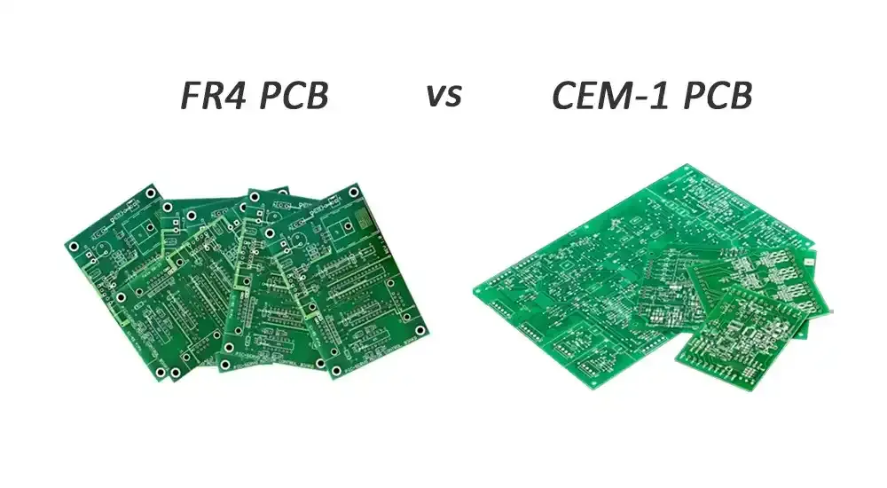
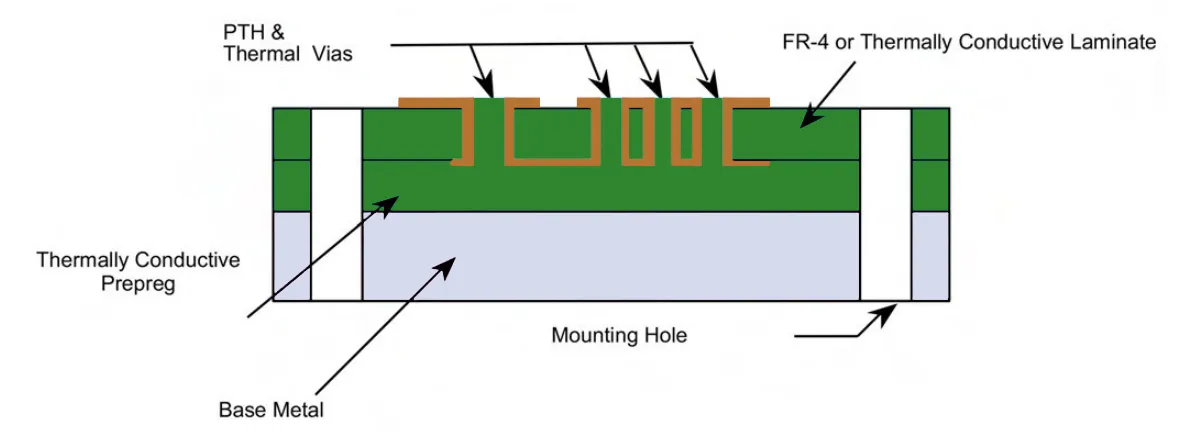
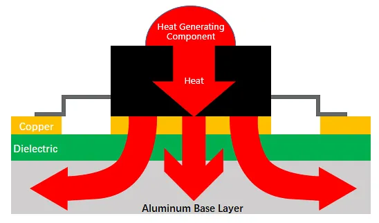
MCPCB consists of a thick metal base layer, a thermally conductive dielectric, and a thin copper circuit layer, distinguishing it from standard FR-4 boards. The metal core, often aluminum for its balance of conductivity and cost, acts as a heat spreader, channeling heat away from components to the board edges or attached heatsinks. In automotive contexts, MCPCB for automotive use excels where conventional PCBs falter under heat loads from power electronics and motor controls. Factory-driven insights reveal that MCPCBs reduce junction temperatures by spreading heat uniformly, minimizing hotspots that lead to delamination or solder joint fatigue. Reliability improves as the rigid metal core resists warpage during thermal expansion, a common issue in high-temperature PCB designs. Ultimately, adopting MCPCB technology aligns with the need for robust automotive PCB design that withstands under-hood temperatures and vibration stresses over the vehicle's lifecycle.
Thermal Management Principles in MCPCB Technology
Effective thermal management in MCPCBs relies on conduction through the high-thermal-conductivity metal core, which can exceed 200 W/mK for aluminum compared to FR-4's mere 0.3 W/mK. Heat generated by components transfers via the thin dielectric layer, typically 75 to 150 microns thick, optimized for low thermal resistance while maintaining electrical isolation. In automotive PCB design, engineers must consider coefficient of thermal expansion mismatches between the core, dielectric, and copper to avoid stress cracks during operation. Factory processes incorporate precise lamination under controlled pressure and temperature to ensure void-free bonding, enhancing long-term MCPCB reliability. Simulations during design predict heat flow paths, guiding trace routing directly over the core for maximal dissipation. These principles form the foundation for thermal PCB automotive performance, enabling sustained operation in environments prone to rapid temperature fluctuations.
Key Design Considerations for Automotive MCPCB Reliability
Designing MCPCBs for automotive applications starts with selecting core thickness, typically 1.0 to 1.5 mm, to balance rigidity and heat spreading without excessive weight. Traces carrying high currents require wider widths and positioning over the core to leverage its conductivity, while avoiding sharp bends that could impede flow. Component placement prioritizes power devices centrally or near edges for heatsink attachment, with thermal pads filling gaps to the core. In factory production, adherence to qualification specs like IPC-6012 ensures the board meets performance criteria for electrical, mechanical, and thermal properties. Vias, if used, demand filled or plugged designs to prevent core exposure and maintain integrity under vibration. These practices directly contribute to high-temperature PCB durability, reducing failure risks in engine compartments or battery management systems.
Manufacturing Best Practices for MCPCB Reliability
From a factory perspective, MCPCB fabrication begins with surface preparation of the metal core to promote adhesion, followed by dielectric coating via rolling or lamination. Etching the copper layer requires photoresist application suited for single-sided structures common in MCPCBs, preserving the core's flatness. Solder mask application protects traces while allowing thermal vias or pads for component attachment. Quality control involves cross-section analysis to verify dielectric thickness uniformity, critical for MCPCB reliability under thermal stress. Assembly processes follow guidelines such as J-STD-001 for soldered connections, ensuring joints withstand automotive vibrations and cycles. Post-fabrication, boards undergo thermal shock testing to simulate real-world conditions, confirming no delamination occurs.
Testing and Qualification for High-Temperature Performance
Reliability testing for MCPCBs in automotive use includes thermal cycling to evaluate expansion behavior across operating ranges. Vibration tests replicate road conditions, assessing mechanical integrity of solder joints and core bonds. Factory protocols incorporate acceptability criteria from IPC-A-600 to inspect for defects like voids or plating anomalies post-plating. High-temperature storage exposes boards to prolonged heat, monitoring for dielectric degradation or trace lift-off. These evaluations ensure thermal PCB automotive solutions deliver consistent performance. Data from such tests guides iterative design refinements, bolstering overall system dependability.
Practical Troubleshooting in MCPCB Automotive Designs
Common challenges in MCPCB for automotive include core warpage from asymmetric heating, addressed by symmetric layouts and controlled cooling rates in manufacturing. Excessive heat concentration around vias prompts redesign with copper-filled types or elimination where possible. Solder joint failures under vibration signal needs for underfill or enhanced pad designs per assembly standards. Factory insights recommend finite element analysis early to predict stress points. Monitoring impedance changes post-cycling detects early insulation breakdown. Resolving these ensures high MCPCB reliability in field applications.
Conclusion
MCPCB technology stands out in automotive PCB design for its unmatched thermal dissipation and structural stability, essential for high-reliability electronics. By integrating metal cores with optimized dielectrics, designers achieve superior heat management vital for power-hungry systems. Factory best practices, from lamination to testing, align with industry standards to deliver robust thermal PCB automotive solutions. Prioritizing these elements minimizes failures, supports longer service life, and meets the demands of modern vehicles. Engineers benefit from structured approaches that enhance MCPCB reliability and high-temperature PCB performance across diverse applications.
FAQs
Q1: What makes MCPCB for automotive superior to standard FR-4 in thermal management?
A1: MCPCBs feature a metal core that conducts heat far more efficiently than FR-4, spreading it uniformly to prevent hotspots. Factory processes ensure thin, high-conductivity dielectrics maintain electrical isolation while minimizing thermal resistance. This setup supports automotive PCB design under high power loads, reducing component temperatures and extending reliability. Vibration resistance improves due to the core's rigidity.
Q2: How does MCPCB reliability impact high-temperature PCB automotive applications?
A2: MCPCB reliability stems from reduced warpage and better CTE matching, preventing cracks during thermal cycles common in vehicles. Standards-aligned manufacturing verifies bond integrity through inspections. In engine bays or EV batteries, this translates to fewer failures and consistent performance. Designers gain confidence in long-term operation.
Q3: What are key best practices in automotive PCB design using MCPCB?
A3: Position high-power components over the core, use wide traces for current paths, and simulate heat flow pre-production. Avoid unnecessary vias to preserve core continuity, opting for edge connections to heatsinks. Factory-driven quality checks per IPC guidelines ensure fabrication precision. These steps optimize thermal PCB automotive efficiency.
Q4: How is MCPCB tested for automotive environments?
A4: Testing involves thermal cycling, vibration, and high-temperature storage to mimic real conditions. Acceptability inspections follow IPC-A-600 criteria for defects. Solder joint integrity checks align with J-STD-001. Results confirm MCPCB reliability for harsh use.
References
IPC-6012E — Qualification and Performance Specification for Rigid Printed Boards. IPC, 2017
IPC-A-600K — Acceptability of Printed Boards. IPC, 2020
J-STD-001G — Requirements for Soldered Electrical and Electronic Assemblies. IPC, 2017