Introduction
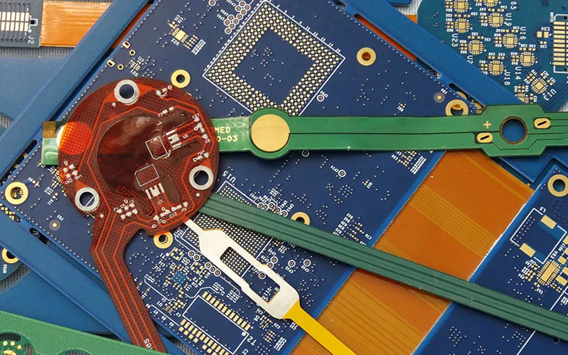
Flex and rigid-flex multi-layer printed circuit boards represent advanced solutions in modern electronics, enabling compact designs that withstand mechanical stress and dynamic environments. These boards combine flexibility with multi-layer capabilities to support complex circuitry in limited spaces, crucial for industries demanding reliability under movement or vibration. Engineers must consider design intricacies from the outset to ensure performance and manufacturability. This article explores flexible PCB design guidelines, rigid-flex PCB stackup configurations, material selection for flex PCBs, bonding techniques, and key applications. Factory perspectives highlight how adherence to standards like IPC-6013 shapes production outcomes.
Multi-layer flex boards extend beyond single or double-layer variants by incorporating additional copper layers separated by dielectrics, allowing for higher density and signal integrity. Rigid-flex variants integrate rigid sections for component mounting with flexible tails for interconnection. Manufacturing these boards requires precise control over lamination and material compatibility to avoid delamination or cracking.
Defining Flex and Rigid-Flex Multi-Layer PCBs and Their Relevance
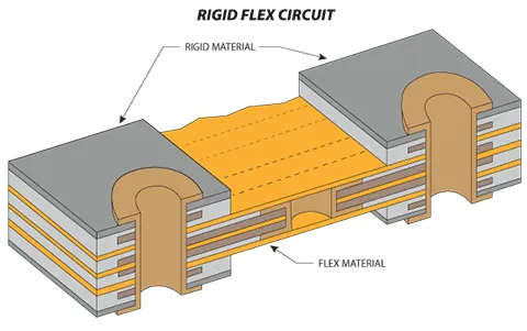
Flex PCBs consist entirely of flexible substrates and conductors, designed to bend repeatedly without failure, while rigid-flex PCBs merge rigid FR-4 sections with flex areas for hybrid functionality. Multi-layer configurations in flex PCBs involve stacking copper foils with flexible dielectrics, enabling complex routing in a thin profile. These boards matter in applications where space constraints and mechanical flexibility outperform traditional rigid boards. Production factories prioritize them for reduced assembly steps, as interconnects integrate seamlessly, minimizing connectors and failure points.
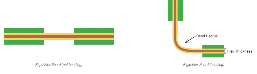
The relevance stems from evolving demands in portable and wearable devices, where traditional PCBs fail due to bulkiness or rigidity. Rigid-flex designs support 3D packaging, folding to fit irregular shapes while maintaining electrical continuity. From a manufacturing viewpoint, these boards demand specialized processes but yield higher reliability in end-use. Standards such as IPC-2223 provide sectional design guidelines to balance flexibility and structural integrity.
Core Technical Principles in Design and Stackup
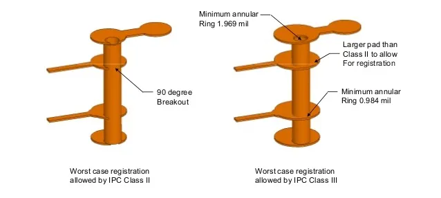
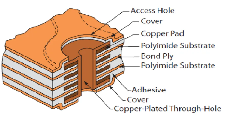
Flexible PCB design guidelines emphasize layer symmetry to position traces near the neutral bending axis, reducing strain during flexure. In multi-layer flex, copper layers alternate with polyimide dielectrics, and traces route perpendicular between layers to distribute stress evenly. Vias in bend zones must avoid placement to prevent cracking, with annular rings oversized for reliability. Factory lamination processes build these stackups sequentially, ensuring adhesion integrity across layers.
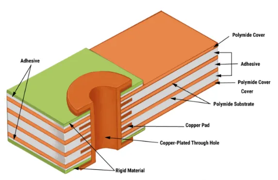
Rigid-flex PCB stackup integrates flex cores between rigid multilayers, typically with rigid sections comprising FR-4 cores and prepregs, transitioning to polyimide flex tails. The stackup diagram reveals rigid arms with through vias and flex sections with blind or filled vias for interlayer connection. Designers specify coverlay on flex areas instead of liquid soldermask to maintain flexibility. Material thickness controls overall bend capability, with thinner flex sections enabling tighter radii.
Signal integrity in high-layer counts requires controlled impedance, achieved by precise dielectric constants in the stackup. Manufacturing inspections verify stackup alignment using cross-section analysis post-lamination. Asymmetry in flex layers leads to warpage, countered by balanced copper distribution.
Material Selection for Flex PCBs
Material selection for flex PCBs centers on substrates that endure repeated bending, thermal cycling, and environmental exposure. Polyimide films dominate due to high thermal stability up to 260 degrees Celsius and excellent chemical resistance, forming the core dielectric. Rolled annealed copper provides ductility for flexing, unlike electrodeposited copper used in rigid boards. Adhesiveless laminates integrate copper directly onto polyimide via sputtering, eliminating weak adhesive interfaces for dynamic applications.
Coverlay materials, typically polyimide with adhesive, protect outer layers while preserving bendability. For high-frequency needs, low-loss dielectrics like LCP offer dimensional stability. Factory qualification per IPC-6013 tests material performance under flex cycles and humidity. Coverlay application replaces soldermask to avoid cracking in bends.
Stiffeners, often polyimide or FR-4, attach to flex tails for connector support without compromising core flexibility. Selection balances thickness with bend radius requirements. Production yields improve with compatible CTE-matched materials across stackup.
Related Reading: Constraint Management Techniques for Flexible and Rigid Flex PCBs
Bonding Techniques in Manufacturing
Bonding techniques secure layers in multi-layer flex and rigid-flex PCBs, with choices impacting reliability. Adhesive-based bonding uses acrylic or epoxy films between copper and polyimide, applied under heat and pressure in lamination presses. Sequential lamination builds rigid-flex by bonding flex cores to rigid multilayers in stages, preventing flex damage from high rigid cure temperatures. Coverlay bonds via thermal lamination, ensuring uniform pressure to avoid voids.
Adhesiveless processes employ laser-drilled vias or plasma etching for direct copper-polyimide attachment, ideal for high-reliability dynamic flex. Factory processes control bondline thickness to under 50 microns for minimal stress concentration. IPC-2223 outlines design rules for bond areas, including overlap and via fencing.
Prepregs bond rigid sections, with no-flow varieties suiting flex transitions. Post-bond inspections use C-scan ultrasonics for delamination detection. Technique selection aligns with layer count and application demands.
Related Reading: Flexible PCB Manufacturing Equipment: Handling Thin and Bendable Substrates
Manufacturing Considerations for Multi-Layer Flex and Rigid-Flex
To achieve high-yield results, engineers must follow a comprehensive guide to flex and rigid-flex PCB manufacturing throughout the production cycle. Manufacturing multi-layer flex starts with core preparation, etching copper patterns on polyimide laminates. Lamination cycles alternate with imaging steps, demanding precise registration for vias. Flex tails receive coverlay post-etch, aligned via fiducials. Rigid-flex assembly laminates rigid multilayers around flex cores using cover sheets to isolate flex during rigid press cycles.
Plating fills or tents vias in flex to avoid chemical attack during flexing. Solder mask applies selectively, avoiding bend zones. Factories employ flying probe testing for continuity before stiffener attachment. Outline routing uses specialized tools to prevent tearing in flex sections.
Environmental controls maintain humidity below 50% to avert polyimide moisture absorption. Final bow and twist measurements ensure flatness in rigid areas. Yield optimization relies on DFM reviews early in design.
Applications of Flex and Rigid-Flex PCBs
Applications of flex and rigid-flex PCBs span medical devices like pacemakers and endoscopes, where miniaturization and biocompatibility matter. Aerospace harnesses them for vibration-resistant avionics, folding into airframes. Automotive uses include sensor arrays in engines and cameras, enduring thermal swings. Wearables integrate flex tails for body-conforming circuits.
Consumer electronics employ rigid-flex in smartphones and laptops for hinge mechanisms, reducing connector wear. Military gear benefits from lightweight, deployable designs. High-layer rigid-flex supports computing in drones. Production scales these for volume via panelized arrays.
Best Practices and Standards Compliance
Adopt flexible PCB design guidelines by simulating bends via FEA to predict stress. Rigid-flex stackups demand iterative DFM with manufacturers for lamination feasibility. Material selection verifies datasheets for flex life cycles. Bonding techniques favor adhesiveless for fatigue-prone areas.
Compliance with IPC-6013 ensures qualification through thermal shock and flex endurance tests. IPC-A-600 sets acceptability criteria for surface and internal features. Factories document processes per ISO 9001 for traceability.
Conclusion
Flex and rigid-flex multi-layer PCBs offer unmatched versatility for demanding applications, guided by precise design and manufacturing. Key elements like stackup symmetry, polyimide selection, and sequential bonding drive success. Engineers benefit from standard-aligned practices to mitigate risks. Future trends lean toward finer pitches and higher layers, reinforcing these boards' role in innovation.
FAQs
Q1: What are essential flexible PCB design guidelines for multi-layer boards?
A1: Flexible PCB design guidelines stress symmetrical stackups to minimize bending stress, avoiding vias in flex zones, and using RA copper for ductility. Traces alternate directions between layers, with teardrop pads enhancing reliability. Coverlay protects bends better than soldermask. Factories recommend DFM checks for bend radii and stiffener placement to boost yields.
Q2: How does rigid-flex PCB stackup affect performance?
A2: Rigid-flex PCB stackup features rigid FR-4 cores sandwiching flex polyimide sections, ensuring smooth transitions via blind vias. Symmetry in flex areas controls impedance and reduces warpage. Manufacturing aligns layers precisely during sequential lamination. This configuration supports high-density routing while enabling 3D folding.
Q3: What factors influence material selection for flex PCBs?
A3: Material selection for flex PCBs prioritizes polyimide for thermal and flex endurance, paired with adhesiveless copper for dynamic use. LCP suits high-frequency with low loss. Coverlay and stiffeners add protection. Compatibility with CTE prevents delamination in multi-layers. Factory testing per standards verifies suitability.
Q4: What bonding techniques improve rigid-flex reliability?
A4: Bonding techniques include sequential lamination for flex-rigid integration and thermal coverlay application. Adhesiveless methods enhance fatigue resistance. Prepregs secure rigid sections without stressing flex. Uniform pressure avoids voids, inspected via cross-sections. These ensure interlayer integrity under mechanical loads.
References
IPC-6013 — Qualification and Performance Specification for Flexible and Rigid-Flex Printed Boards. IPC
IPC-2223 — Sectional Design Standard for Flexible/Rigid-Flexible Printed Boards. IPC
IPC-A-600 — Acceptability of Printed Boards. IPC