Introduction
Medical device PCB assembly demands precision and reliability because these components power life-critical equipment like pacemakers, diagnostic imagers, and patient monitors. Engineers face unique challenges in balancing complex circuitry with stringent regulatory compliance to prevent failures that could endanger patients. PCB quality control becomes paramount, integrating automated optical inspection, X-ray analysis, and functional testing to verify solder joint integrity and component placement. Regulatory compliance, particularly through frameworks like FDA requirements and ISO 13485 pcb assembly processes, ensures traceability from design to deployment. This article explores practical strategies for achieving high-reliability assemblies, troubleshooting common issues, and implementing robust quality assurance. By adhering to established standards, electric engineers can mitigate risks and deliver assemblies that meet performance expectations in demanding medical environments.

Why Regulatory Compliance Matters in Medical Device PCB Assembly
Regulatory compliance in medical device PCB assembly safeguards patient safety while streamlining market access. Non-compliance can lead to device recalls, legal liabilities, and halted production, as seen in cases where solder voids or contamination caused intermittent failures. FDA pcb assembly oversight under 21 CFR Part 820 mandates quality system regulations that emphasize design controls, process validation, and corrective actions. Similarly, ISO 13485 establishes a quality management system tailored for medical devices, requiring documented procedures for risk assessment and supplier qualification. Electric engineers must integrate these into assembly workflows to address potential failure modes like delamination from thermal stress or ionic residues accelerating corrosion. Ultimately, compliance not only fulfills legal obligations but also enhances assembly yield and long-term device reliability.
Key Regulations and Standards Governing Medical Device PCB Assembly
Medical device PCB assembly aligns with multiple layers of oversight, starting with FDA regulations that classify devices by risk and impose corresponding manufacturing controls. For higher-risk Class II and III devices, assemblies must demonstrate consistent performance through validated processes and lot traceability. ISO 13485 pcb assembly certification drives this by mandating risk-based thinking, where engineers identify hazards like component misalignment during reflow and implement mitigations such as profile optimization. IPC standards complement these by defining assembly criteria; for instance, Class 3 requirements ensure high-reliability solder joints capable of withstanding vibration and humidity in implantable devices.
Electric engineers specify Class 3 per IPC-A-610 for visual and mechanical acceptability, scrutinizing fillet wetting, hole fill, and lead coplanarity to prevent opens or shorts. J-STD-001 outlines soldering requirements, including flux application limits and preheat profiles to minimize defects like bridging. These standards, referenced sparingly across processes, provide measurable benchmarks without overlapping regulatory demands. Compliance audits verify adherence, often revealing gaps in documentation that engineers can address proactively.
Related Reading: Ensuring PCB Reliability: A Deep Dive into Solder Joint Voids
Essential PCB Quality Control Processes for Medical Assemblies
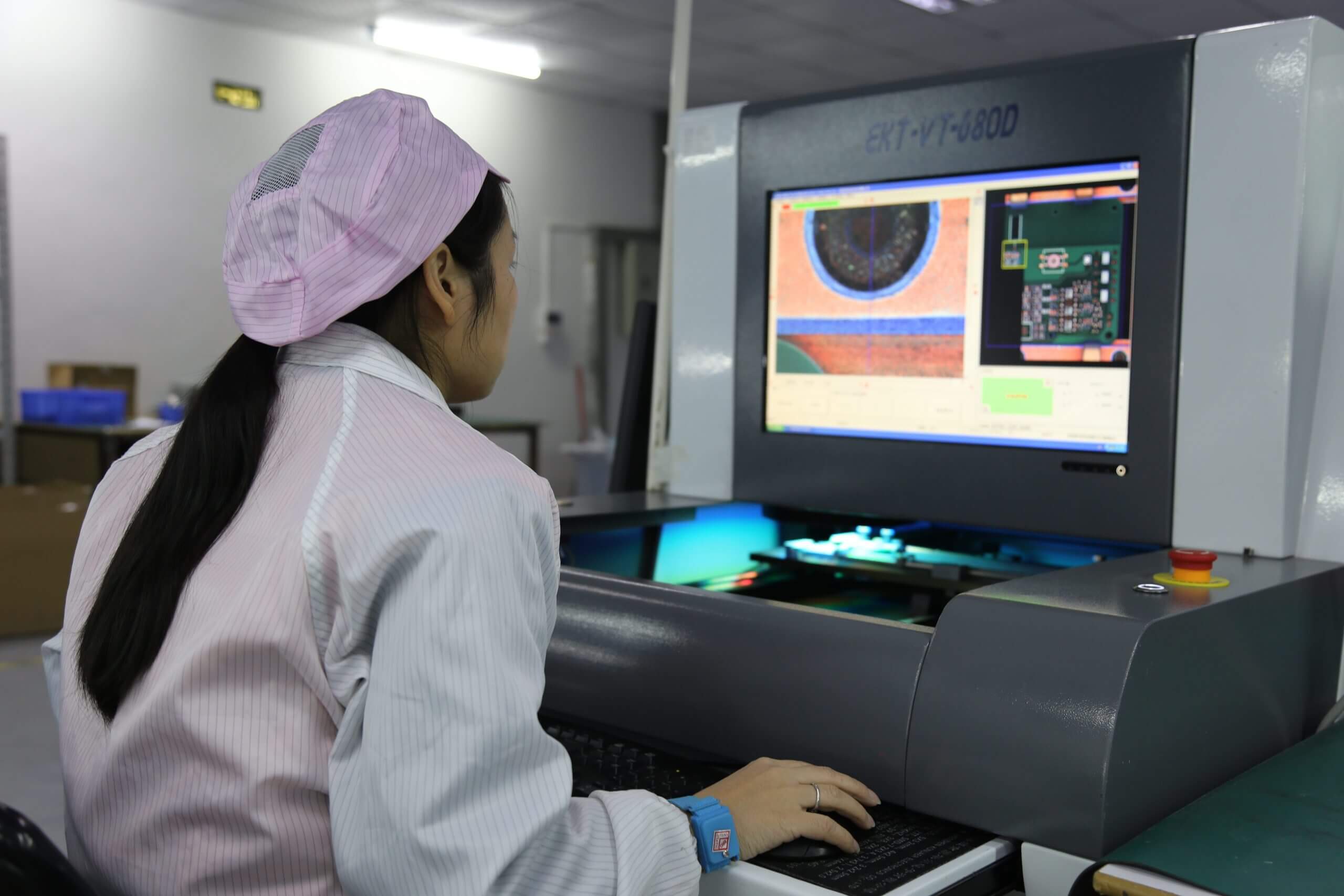
PCB quality control in medical device assembly spans incoming inspection through final verification, forming a multi-tiered defense against defects. Upon receipt, bare boards undergo dimensional checks and surface cleanliness testing to confirm compliance with fabrication specs, catching warpage or contamination early. Surface mount technology placement demands automated verification of fiducials and component orientation, with offsets exceeding tolerances triggering rework.
Post-reflow, automated optical inspection (AOI) detects anomalies like tombstoning or insufficient solder volume, while X-ray imaging reveals subsurface issues in BGAs, such as head-in-pillow defects. Functional testing simulates operational stresses, including thermal cycling and in-circuit measurements, to validate signal integrity. Ionic contamination testing via ROSE method quantifies residues that could lead to electrochemical migration under bias. Engineers troubleshoot by correlating defect data to process parameters, adjusting stencil apertures or reflow zones iteratively.
Manual visual inspection per IPC-A-610 Class 3 criteria supplements automation, focusing on subtle flaws like microcracks in castellations. Statistical process control charts track metrics like first-pass yield, flagging drifts before they impact batches. This layered approach ensures assemblies meet regulatory compliance thresholds for reliability.
Related Reading: AOI Programming for Dummies: A Step by Step Guide to PCB Inspection
Best Practices for Achieving ISO 13485 and FDA Compliance in PCB Assembly
Implement a traceability system from Gerber files through to serialized units, using barcodes and MES software to log every process step. This supports root cause analysis during audits or field returns, a core ISO 13485 requirement. Validate assembly equipment via IQ/OQ/PQ protocols, establishing baselines for pick-and-place accuracy and oven uniformity to prevent systematic errors.
Engineer risk management by conducting FMEAs on potential failure modes, such as ESD damage during handling, and deploy mitigations like grounded workstations and humidity controls. Source components from qualified suppliers with lot-level certificates, performing 100% incoming AOI for critical passives. For fda pcb assembly, document design inputs against outputs, ensuring layout supports cleanability and sterilization if needed.
Optimize reflow profiles with thermocouples on test coupons, targeting peak temperatures that avoid alloy segregation while achieving full melt. Employ no-clean fluxes to minimize residues, verified post-assembly. Train operators to IPC J-STD-001 criteria, refreshing certifications annually. These practices reduce variability, boosting confidence in medical device performance.
Troubleshooting Common Challenges in Medical Device PCB Assembly
Misalignment during high-speed placement often stems from stencil wear or board warp; engineers counter this by using step stencils and laser-cut apertures matched to pad sizes. Solder beading under BGAs signals excessive paste volume, resolved by finer powder types or shear thinning optimizations. Component overheating in reflow appears as discoloration, troubleshooted by zone profiling to extend soak times without flux burnout.
Contamination hotspots trace to poor housekeeping; implement laminar flow hoods and daily swab tests. For fine-pitch QFNs, voiding under thermal pads improves with via-in-pad designs venting gases. Yield drops from board-level warpage demand carrier fixturing during assembly. Post-process baking removes moisture before reflow, preventing popcorn cracks. Data logging from inline monitors pinpoints trends, enabling predictive maintenance.
Conclusion
Medical device PCB assembly hinges on rigorous regulatory compliance and pcb quality control to deliver unflinching reliability. By leveraging ISO 13485 frameworks, FDA guidelines, and IPC standards, engineers construct assemblies resilient to real-world stresses. Practical troubleshooting refines processes, minimizing defects and ensuring traceability. Prioritizing these elements not only meets mandates but elevates device safety and performance. Electric engineers equipped with these insights can navigate complexities, driving innovation in healthcare technology.
FAQs
Q1: What role does ISO 13485 play in medical device PCB assembly?
A1: ISO 13485 pcb assembly certification enforces a quality management system focused on risk mitigation, process validation, and full traceability. Engineers document supplier qualifications, assembly validations, and change controls to comply. This standard aligns with FDA expectations, reducing audit findings and enhancing assembly consistency for critical devices. Practical implementation involves regular internal audits and CAPA processes.
Q2: How does PCB quality control differ for medical versus consumer electronics?
A2: Medical pcb quality control mandates Class 3 IPC criteria, 100% inspections, and advanced testing like X-ray for hidden defects, unlike consumer Class 2 tolerances. Traceability to the component level supports failure investigations, with stricter cleanliness and ESD protocols. Engineers prioritize zero-defect goals through SPC and FMEA, ensuring long-term reliability under sterilization or implantation stresses.
Q3: What are key steps for FDA compliance in PCB assembly?
A3: Fda pcb assembly requires adherence to 21 CFR Part 820 via design controls, process validation, and complaint handling. Implement DFM reviews early, validate reflow profiles, and maintain production records for audits. Risk-based sampling verifies outgoing quality, with engineers focusing on biocompatibility materials and hermetic sealing where applicable.
Q4: Why is Class 3 IPC compliance essential for medical PCBs?
A4: Class 3 per IPC-A-610 and J-STD-001 demands superior solder joint strength and minimal voids for high-reliability medical applications. It addresses vibration, thermal cycling, and humidity, preventing failures in life-support devices. Engineers verify via cross-sections and accelerated life testing, troubleshooting fillet issues proactively.
References
ISO 13485:2016 — Medical devices — Quality management systems — Requirements for regulatory purposes. ISO, 2016
IPC-A-610J — Acceptability of Electronic Assemblies. IPC, 2024
IPC J-STD-001J — Requirements for Soldered Electrical and Electronic Assemblies. IPC, 2024