Introduction
In the fast-paced world of electronics, printed circuit board (PCB) design demands precision to ensure functionality and reliability. As systems grow more complex with high-speed signals and dense layouts, engineers face challenges like signal degradation, thermal issues, electromagnetic interference (EMI), and power delivery inconsistencies. Simulation plays a pivotal role in addressing these concerns before fabrication begins. By leveraging tools for signal integrity simulation, thermal simulation, EMI simulation, power integrity simulation, and circuit simulation, designers can predict performance and avoid costly redesigns. This article explores how simulation transforms PCB design, offering electrical engineers practical insights into its mechanisms and benefits. From identifying potential failures to optimizing layouts, simulation is an indispensable step in modern engineering workflows for achieving robust and efficient designs.
What Is Simulation in PCB Design and Why It Matters
Simulation in PCB design refers to the use of specialized software to model and analyze the behavior of a circuit board under various conditions. It enables engineers to predict how a PCB will perform in terms of electrical, thermal, and electromagnetic characteristics before physical prototyping. This process is critical because modern electronics often operate at high frequencies or under stringent power constraints, where even minor issues can lead to system failures.
The importance of simulation lies in its ability to reduce risks and save resources. Without it, engineers might only discover problems during testing or after deployment, leading to expensive iterations. By incorporating signal integrity simulation, thermal simulation, EMI simulation, power integrity simulation, and circuit simulation, designers can ensure compliance with industry standards and meet performance expectations. For electrical engineers, simulation is not just a tool but a fundamental part of the design process to achieve reliability and efficiency.
Technical Principles of Simulation in PCB Design
Signal Integrity Simulation
Signal integrity simulation focuses on ensuring that electrical signals maintain their quality as they travel through a quick turn PCB. It analyzes factors like impedance mismatches, crosstalk, and signal reflections that can distort data transmission. This type of simulation is vital for high-speed designs where timing and accuracy are critical. By modeling transmission lines and terminations, engineers can identify potential issues and adjust trace layouts or add termination resistors to maintain signal fidelity.
Suggested Reading: Mastering PCB Impedance Simulation for High-Speed Designs
Thermal Simulation
Thermal simulation evaluates how heat dissipates across a PCB during operation. It helps identify hotspots that could damage components or degrade performance. By simulating power dissipation and airflow, engineers can optimize component placement and select appropriate materials to manage temperature. This process is crucial for designs with high-power components, ensuring compliance with thermal limits specified in standards like IPC-2152 for current-carrying capacity.
EMI Simulation
EMI simulation assesses the electromagnetic interference that a PCB might emit or be susceptible to. It models radiation patterns and coupling effects to ensure the design does not interfere with nearby systems or fail under external noise. This simulation is essential for meeting regulatory requirements and maintaining system reliability. Engineers can use the results to adjust shielding, grounding strategies, and component placement for minimal interference.
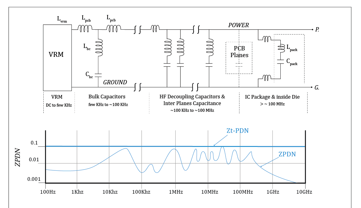
Power Integrity Simulation
Power integrity simulation examines the stability of power delivery networks within a PCB. It analyzes voltage drops, noise, and decoupling capacitor effectiveness to ensure consistent power supply to components. This is particularly important in designs with multiple voltage rails or high-current demands. By simulating the power distribution network, engineers can optimize capacitor placement and trace widths to prevent performance issues.
Circuit Simulation
Circuit simulation focuses on the overall electrical behavior of the PCB, including component interactions and system response. It verifies that the design meets functional requirements under various operating conditions. This type of simulation often integrates with other analyses to provide a comprehensive view of performance. Electrical engineers rely on circuit simulation to validate designs before moving to fabrication, ensuring all elements work as intended.
Practical Applications of Simulation in PCB Design
Predicting Performance Issues
Simulation allows engineers to predict performance issues before they manifest in physical prototypes. For instance, signal integrity simulation can reveal timing errors in high-speed data lines, enabling adjustments to trace lengths or impedance. Similarly, thermal simulation can highlight areas of excessive heat buildup, prompting the addition of vias or heat sinks. By addressing these concerns early, engineers avoid delays and ensure the design performs as expected.
Avoiding Costly Redesigns
One of the most significant benefits of simulation is its role in preventing costly redesigns. Identifying problems like EMI susceptibility or power delivery failures during the design phase is far less expensive than correcting them after manufacturing. Power integrity simulation, for example, can ensure stable voltage levels across the board, avoiding component damage. This proactive approach aligns with best practices outlined in standards like IPC-6012E for rigid board performance.
Optimizing Layout and Component Placement
Simulation provides actionable data to optimize PCB layouts. EMI simulation can guide the placement of sensitive components away from noise sources, while thermal simulation informs spacing to enhance heat dissipation. Engineers can iterate designs virtually, testing multiple configurations without physical prototypes. This optimization reduces material waste and ensures the final product meets both performance and reliability goals.
Ensuring Compliance with Standards
Compliance with industry standards is non-negotiable in PCB design. Simulation helps verify that designs adhere to guidelines set by organizations like IPC and IEC. For example, thermal simulation ensures current-carrying traces meet the requirements of IPC-2152, while EMI simulation aids in meeting electromagnetic compatibility criteria. By integrating these checks into the design process, engineers can confidently produce boards that pass certification tests.
Best Practices for Implementing Simulation in PCB Design
Start Early in the Design Process
Begin simulation at the schematic stage to catch potential issues before layout completion. Early signal integrity simulation can influence routing decisions, while initial power integrity simulation ensures proper decoupling strategies. This approach minimizes rework and aligns with efficient design workflows recommended by industry standards.
Use Accurate Models and Data
Accurate simulation results depend on precise component models and material properties. Ensure that data for dielectric constants, thermal conductivity, and electrical characteristics are up to date. Refer to standards like JEDEC J-STD-020E for component behavior under stress to enhance model reliability. Inaccurate inputs lead to misleading outputs, so validation of data is critical.
Integrate Multiple Simulation Types
Combine signal integrity simulation, thermal simulation, EMI simulation, power integrity simulation, and circuit simulation for a holistic view of PCB performance. Each type addresses specific aspects, and their integration reveals interactions between electrical, thermal, and electromagnetic domains. This comprehensive analysis ensures no critical issue is overlooked during design.
Iterate and Validate Results
Simulation is an iterative process. After initial runs, analyze results, make adjustments, and simulate again. Validate findings against known benchmarks or standards like IPC-A-600K for board acceptability. Iteration refines the design, ensuring it meets performance criteria before moving to prototyping or production stages.
Challenges and Limitations of Simulation in PCB Design
While simulation is a powerful tool, it has limitations that engineers must recognize. Results depend heavily on the quality of input data and models. Incomplete or incorrect information can lead to inaccurate predictions, potentially missing real-world issues. Additionally, simulation cannot fully replicate all environmental factors, such as manufacturing variations or unexpected external interference.
Another challenge is the computational resources required for complex simulations. High-fidelity models for EMI or thermal analysis may demand significant processing power and time, impacting project timelines. Engineers must balance simulation depth with practical constraints, prioritizing critical aspects of the design. Despite these challenges, simulation remains an essential step when used judiciously with validation against physical testing.
Conclusion
Simulation has become a cornerstone of modern PCB design, enabling electrical engineers to predict performance and avoid problems before they arise. Through signal integrity simulation, thermal simulation, EMI simulation, power integrity simulation, and circuit simulation, designers can address a wide range of challenges from signal degradation to thermal management. By integrating these tools early in the design process, optimizing layouts, and ensuring compliance with industry standards, engineers achieve reliable and efficient outcomes. Though simulation has limitations, its benefits in reducing costs and enhancing design quality are undeniable. Embracing best practices in simulation empowers teams to deliver robust PCBs that meet the demands of today’s complex electronics landscape.
FAQs
Q1: How does signal integrity simulation improve PCB performance?
A1: Signal integrity simulation identifies issues like crosstalk and reflections that degrade signal quality in high-speed designs. By modeling transmission lines and impedance, it allows engineers to adjust trace layouts and terminations. This ensures accurate data transmission and prevents timing errors, ultimately enhancing PCB reliability and performance as per industry expectations.
Q2: Why is thermal simulation critical for PCB reliability?
A2: Thermal simulation evaluates heat distribution across a PCB, identifying hotspots that could damage components. It guides optimal placement and material selection to manage temperature effectively. Ensuring compliance with standards like IPC-2152, this process prevents failures due to overheating, making it essential for long-term reliability in demanding applications.
Q3: What role does EMI simulation play in PCB design?
A3: EMI simulation assesses electromagnetic interference risks, both emitted by and affecting the PCB. It helps engineers design shielding and grounding to minimize noise and ensure compatibility with other systems. This step is crucial for meeting regulatory requirements and maintaining system integrity in environments with multiple electronic devices.
Q4: How does power integrity simulation prevent design failures?
A4: Power integrity simulation analyzes voltage stability and noise in power delivery networks. It ensures consistent power supply to components by optimizing capacitor placement and trace widths. This prevents issues like voltage drops that could cause malfunctions, making it a vital tool for reliable PCB operation in complex systems.
References
IPC-2152 — Standard for Determining Current Carrying Capacity in Printed Board Design. IPC, 2009.
IPC-6012E — Qualification and Performance Specification for Rigid Printed Boards. IPC, 2020.
IPC-A-600K — Acceptability of Printed Boards. IPC, 2020.
JEDEC J-STD-020E — Moisture/Reflow Sensitivity Classification for Nonhermetic Surface Mount Devices. JEDEC, 2014.


