Introduction
Single-sided printed circuit boards form the foundation for many everyday consumer electronics, particularly in applications requiring simplicity and cost efficiency. In remote controls for televisions, air conditioners, and other household devices, these boards handle basic circuitry with traces on just one side of the substrate. Electric engineers value single-sided PCBs for their straightforward design, which aligns well with low-complexity circuits involving buttons, LEDs, and infrared transmitters. This article explores the role of single-sided PCBs in remote controls, highlighting a single-sided PCB remote control example and the benefits of single-sided PCBs in such devices. By focusing on technical principles, manufacturing insights, and best practices, engineers can optimize their designs for reliability and manufacturability. Understanding these elements ensures projects meet performance needs without unnecessary complexity.
What Is a Single-Sided PCB and Why It Matters for Remote Controls
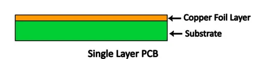
A single-sided PCB features conductive traces, pads, and components confined to one side of a non-conductive substrate, typically FR-4 epoxy laminate, while the opposite side remains bare. This configuration contrasts with double-sided or multilayer boards, limiting interconnections to surface routing only. In remote controls, where circuits manage key inputs, signal processing, and transmission via a microcontroller and IR LED, single-sided construction suffices for the modest routing demands. Engineers select single-sided PCB for consumer products like remotes because it reduces material use and assembly time, making it ideal for high-volume production.
The relevance stems from the low pin count and minimal signal integrity challenges in these devices. Remote control circuits rarely exceed 20-30 components, allowing through-hole or surface-mount parts to connect directly without vias. This simplicity lowers failure points, such as delamination or shorts from multilayer misalignment. For electric engineers designing for cost-sensitive markets, single-sided PCBs enable rapid prototyping and scaling. Moreover, adherence to standards like IPC-6012E ensures the board meets qualification criteria for rigid printed boards, guaranteeing durability in handheld use.
Technical Principles Behind Single-Sided PCBs in Remote Controls
The core principle of single-sided PCBs revolves around copper foil patterning on a single substrate surface, achieved through imaging, etching, and plating processes. Engineers design traces to avoid overlaps by routing signals radially from the microcontroller to peripherals like buttons and the IR transmitter. Component placement prioritizes accessibility, with through-hole leads soldering from the bare side to secure connections mechanically. This setup demands careful layout to manage current paths, especially for battery-powered remotes where power traces must handle peak loads from LED bursts without excessive voltage drop.
Signal integrity remains straightforward due to the absence of vias, which can introduce impedance discontinuities in denser boards. In a single-sided PCB remote control example, the microcontroller's output pin connects directly to the IR LED via a current-limiting resistor, with ground returns sharing the substrate plane if needed. Thermal management relies on copper pour areas to dissipate heat from the chip during transmission pulses. Engineers must account for parasitic capacitance between traces, spacing them per IPC-A-600K guidelines for acceptability to prevent crosstalk in close-proximity layouts.
Electromechanical considerations include button domes or tactile switches mounted to align with traces, ensuring reliable contact under repeated presses. The board's rigidity supports enclosure integration, with mounting holes positioned to avoid stress on solder joints. Substrate thickness, often 1.6 mm, balances flexibility for handheld ergonomics and strength against warpage from soldering heat.
Single-Sided PCB Manufacturing for Remotes: Key Processes
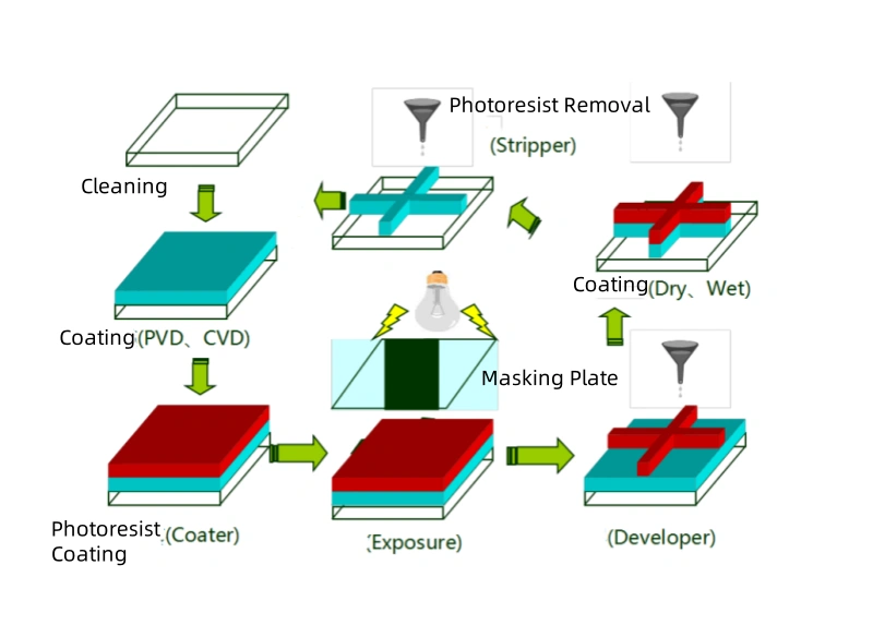
Manufacturing single-sided PCB for consumer products begins with panel preparation, where copper-clad laminates undergo drilling for through-hole components. Photoresist application and UV exposure define the trace pattern, followed by chemical etching to remove excess copper. Post-etch cleaning and tin plating protect traces from oxidation, ensuring solderability. For remote controls, panels process in high volumes, with routing to singulate individual boards precisely to fit enclosures.
Solder mask application coats the copper side, leaving pads exposed for component attachment, while silkscreen adds legends for assembly reference. Electrical testing verifies continuity and shorts using flying probe systems, critical for detecting opens in power traces. Baking removes moisture per JEDEC J-STD-020E guidelines before final packaging, preventing reflow defects in assembly. Factory-driven processes emphasize yield optimization, with panel utilization exceeding 80% for cost control in remote production.
Suggested Reading: Single Sided PCB Assembly: A Step by Step Guide
Quality control integrates visual inspection for trace defects and impedance checks where applicable. Automated optical inspection scans for etching anomalies, aligning with IPC standards for consistent output. Engineers benefit from these steps by specifying panel sizes and tolerances that match remote form factors.
Benefits of Single-Sided PCBs in Remote Control Applications
The primary benefit of single-sided PCBs lies in cost reduction, as they require half the copper and fewer process steps than double-sided boards. In consumer products, this translates to lower per-unit pricing, vital for remotes sold in millions. Manufacturing simplicity cuts lead times, enabling just-in-time production for seasonal demands. Reliability improves with fewer layers prone to registration errors or interlayer shorts.
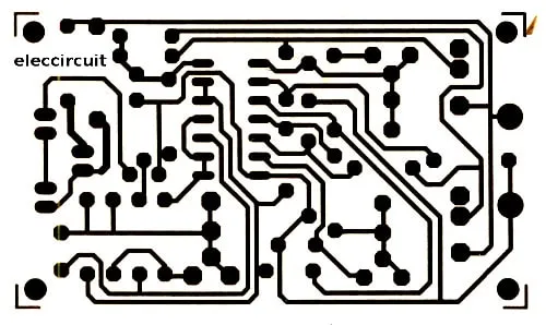
For electric engineers, design freedom focuses on optimization rather than complexity management. A single-sided PCB remote control example demonstrates how a 50 mm by 30 mm board accommodates all functions without jumpers or wire bonds. Power efficiency benefits from direct, short traces minimizing resistance losses in battery operation. Environmental advantages include reduced material waste, supporting sustainability in high-volume runs.
Assembly yields higher first-pass rates, as through-hole soldering secures components firmly against vibration in portable use. Scalability suits prototyping to mass production seamlessly.
Best Practices for Designing and Implementing Single-Sided PCBs for Remotes
Start with schematic capture emphasizing minimal components, selecting low-pin-count microcontrollers like those with 8-20 GPIOs. Layout traces with widths scaled to current: 0.5 mm for signals, 1-2 mm for power. Maintain 0.25 mm spacing minimum to avoid bridging during wave soldering. Place high-current paths away from heat-sensitive parts, using vias sparingly if zero-ohm jumpers prove necessary, though pure single-sided avoids them.
Component selection favors leaded parts for mechanical strength, with SMD options for denser packing. Simulate battery drain to ensure trace drops stay under 100 mV. Prototype on small panels to validate fit in enclosures, iterating on button alignment. During manufacturing handover, specify HASL or ENIG finish for solderability, per J-STD-001 requirements.
Troubleshooting common issues involves checking for warpage post-laminate cure, using fixtures in assembly. Test remotes for IR range and button debounce under accelerated life cycles. For detailed layout optimization techniques, see our guide on single sided PCB best practices.
Case Study: Optimizing a Single-Sided PCB Remote Control Example
Consider a universal remote redesign where engineers consolidated a double-sided board to single-sided, reducing cost by 25% while maintaining functionality. The layout centralized the microcontroller, fanning traces to 12 buttons, battery contacts, and IR LED. Manufacturing for remotes emphasized panel routing with v-scoring for depanelization efficiency. Post-assembly tests confirmed 99% yield, with failures traced to trace width undersizing on power lines, rectified by widening to 1.5 mm.
This single-sided PCB for consumer products example highlights iterative design: initial prototypes revealed LED overheating, addressed by copper pour. Field trials verified 500,000 press cycles durability. Insights underscore standard compliance in etching tolerances for consistent performance.
Conclusion
Single-sided PCBs remain essential for simple remote controls, offering unmatched simplicity, cost savings, and reliability. Electric engineers leverage their design ease and manufacturing efficiency to deliver robust consumer products. By applying technical principles, best practices, and standards like IPC-6012E, projects achieve optimal outcomes. Future trends may integrate flexible variants, but rigid single-sided boards endure as the backbone for basic electronics.
FAQs
Q1: What are the main benefits of single-sided PCBs in remote control designs?
A1: Benefits of single-sided PCBs include lower manufacturing costs due to simpler processes, reduced material usage, and higher assembly yields. They suit low-complexity circuits with direct trace routing, minimizing failure risks from vias or multilayers. For electric engineers, this enables faster prototyping and reliable performance in battery-powered remotes, aligning with high-volume production needs. Standards ensure quality without excess complexity.
Q2: How does single-sided PCB manufacturing for remotes differ from complex boards?
A2: Single-sided PCB manufacturing for remotes focuses on single-layer etching, through-hole drilling, and basic plating, skipping via formation and lamination. Processes emphasize high throughput with panel-based production for cost efficiency. Engineers specify tolerances for trace spacing and solder mask to fit compact enclosures. This streamlined approach boosts yields compared to multilayer fabrication.
Q3: Can you provide a single-sided PCB remote control example for consumer products?
A3: A typical single-sided PCB remote control example features a microcontroller connected to buttons, an IR LED, and battery terminals on a 60 mm by 40 mm FR-4 board. Traces route signals without crossings, using through-hole components for durability. This design powers TV remotes effectively, demonstrating single-sided PCB for consumer products in everyday use with minimal components.
Q4: Why choose single-sided PCBs over double-sided for simple remotes?
A4: Single-sided PCBs excel for simple remotes by avoiding interlayer alignment issues, cutting costs, and simplifying repairs. They handle basic routing needs reliably, with direct soldering for mechanical strength. Electric engineers prefer them for quick iterations and compliance with IPC guidelines, ensuring functionality without performance trade-offs in low-density applications.
References
IPC-6012E — Qualification and Performance Specification for Rigid Printed Boards. IPC, 2018
IPC-A-600K — Acceptability of Printed Boards. IPC, 2020
JEDEC J-STD-020E — Moisture/Reflow Sensitivity Classification of Nonhermetic Solid State Surface Mount Devices. JEDEC, 2014