Introduction
Among the four major topologies, LLC is widely used and often paired with a flyback as an auxiliary power supply. A high-power LLC together with a smaller auxiliary converter defines the typical system boundary conditions.
LLC Resonant Principle
The midpoint nodes of the upper and lower bridge legs produce rectangular drive waveforms. By analyzing their fundamental components, the resonant network can be approximated as being driven by a sinusoidal fundamental. The resonant tank is an LC network that produces resonant current waveforms. The tank impedance can be characterized and the secondary-side impedance reflected to the primary, enabling normalized frequency and gain analysis.
Control keeps the operating point within region 1 or region 2. Output voltage sensing and negative feedback adjust the bridge switching frequency to stabilize the output voltage. The resonant tank behaves approximately as a current source, so the output only requires a capacitor to form the filter; no additional output inductor is necessary.
Advantages of LLC
Resonant LLC operation enables ZVS and ZCS, improving efficiency. The near-sinusoidal form permits higher switching frequency, reducing MOSFET count and transformer size and allowing magnetic integration, which increases power density. High-Q resonant currents also reduce EMI and allow smaller filter components. These characteristics make LLC attractive in many applications.
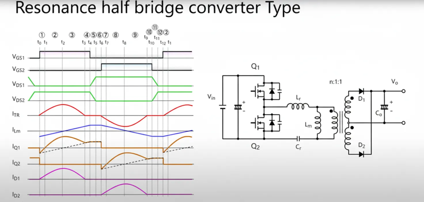
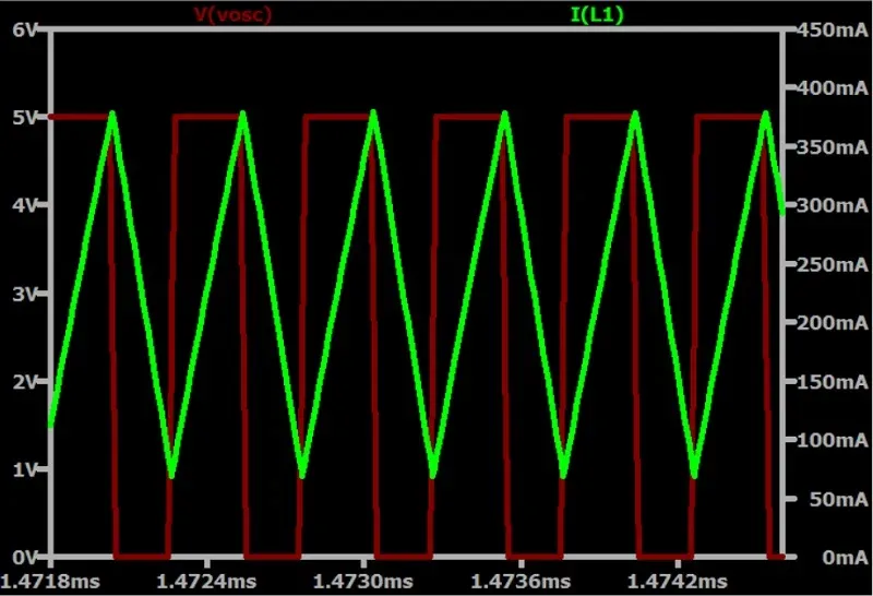
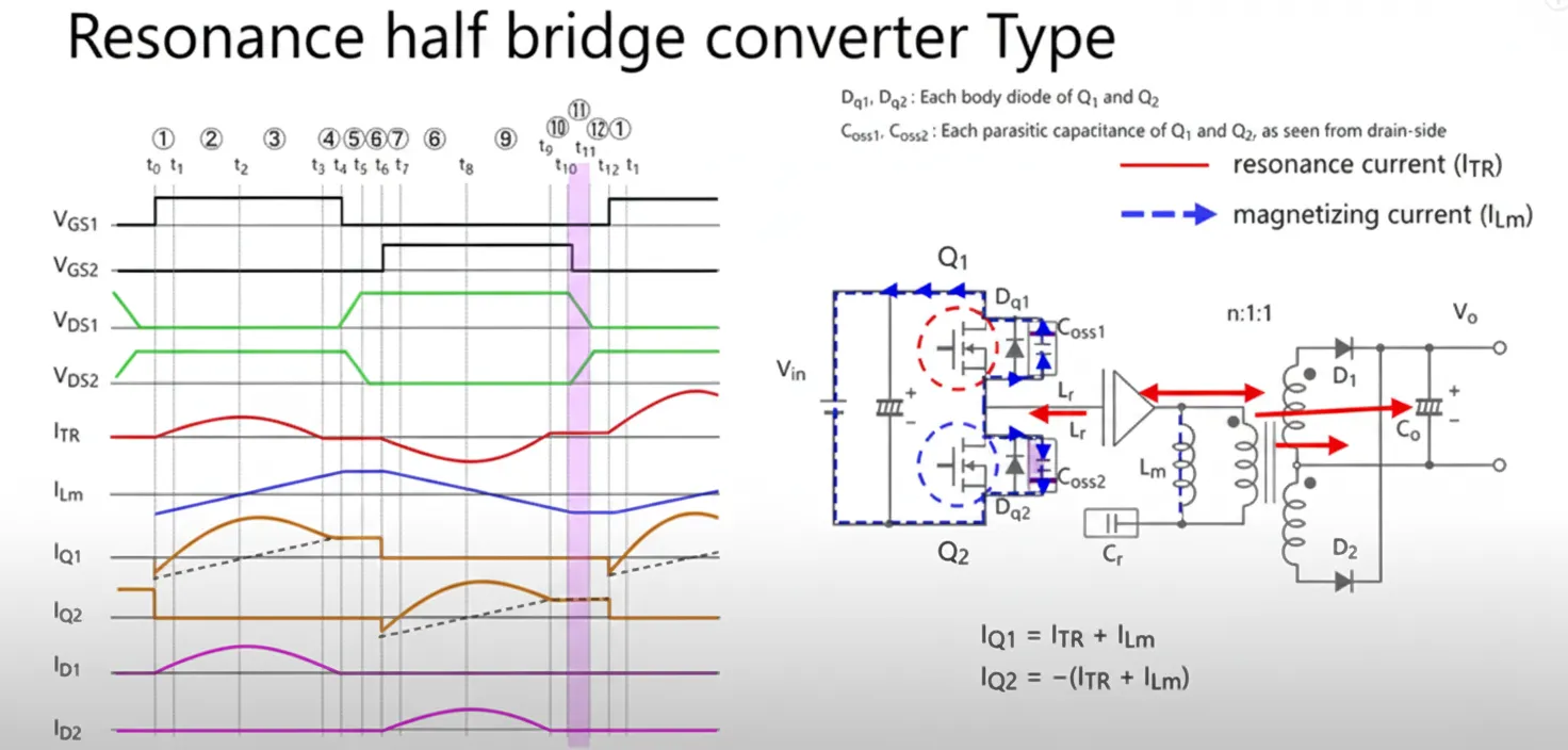
Overview of the 12 States
The 12 states form a repeating cycle. The analysis here assumes the switching frequency is below the resonant frequency, i.e., the switching period is larger than the resonant period. In that case, the VG waveform duration is longer than the resonant current Itr duration, as shown in the figure below.
The cycle can be seen as four main segments. When Q1 conducts, VIN delivers energy through the transformer to the secondary. When the complementary device conducts, the resonant capacitor CR delivers energy. Q1 and Q2 operate complementarily.
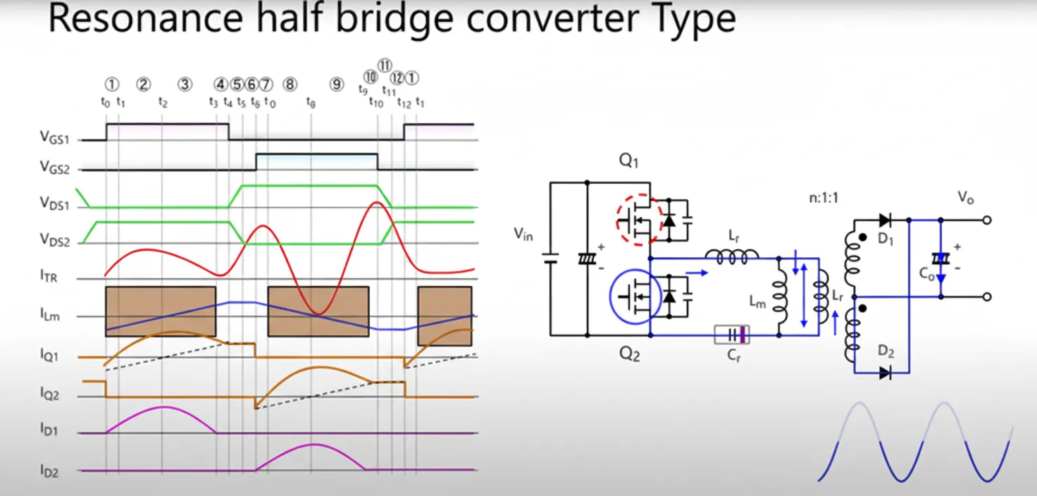
Between Q1 and Q2 conduction there are dead-time intervals. These dead times and conduction intervals produce a 12-state sequence: each transistor conduction interval contains 4 states, and each dead time contains 2 states, for a total of 4 + 2 + 4 + 2 = 12 states. The following explains each state in order.
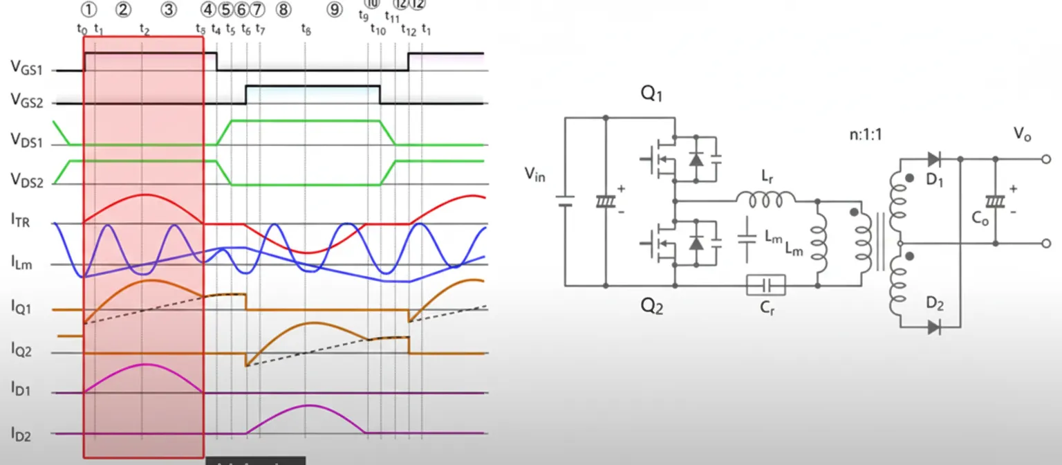
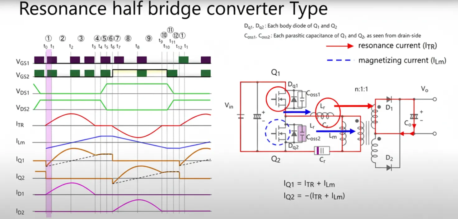
Cycle View Before T0
Before T0, prior to Q1 conduction, the magnetizing current is negative. During the dead time the magnetizing current charges COSS2 and discharges COSS1, interacting with transformer parasitic capacitances. Sufficient magnetizing current is required to fully discharge these capacitances; otherwise ZVS will not be achieved.
T0–T1: Q1 On
When Q1 turns on, the magnetizing current IM flows against the initial polarity. Q1 injects VIN energy into the transformer. Energy transfers through the transformer and diode to the output capacitor C0. The magnetizing inductance LM sees forward voltage, so IM decreases approximately linearly.
T1–T2
From T1 to T2, LM current continues to ramp down to zero and then reverses. The resonant current reaches a peak and then decreases while still charging C0 through D1. The magnetizing inductance is influenced by the secondary-side load, causing LM to increase linearly in the forward direction. The resonant behavior is driven partly by the voltage source and partly by the demagnetization of the magnetizing inductance, so the system exhibits both voltage-source-like and current-source-like behaviors.
T2–T3
Between T2 and T3 the resonant current declines while continuing to charge CR. The magnetizing current increases. When resonant current and magnetizing current equalize, the circuit transitions into the next state. In this interval the resonant current and magnetizing current flow in the same direction and reinforce each other.
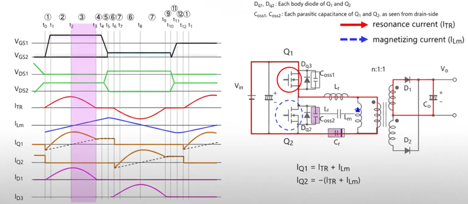
T3–T4
At this point the magnetizing and resonant currents are similar and energy transfer to the secondary ceases. LM is no longer dominated by the secondary load, so the resonant behavior involves LM + LR and CR. Since LM is relatively large, the resonant current Itr can be approximated as nearly constant. Effectively the resonant current component is small and the magnetizing current circulates through Q1.
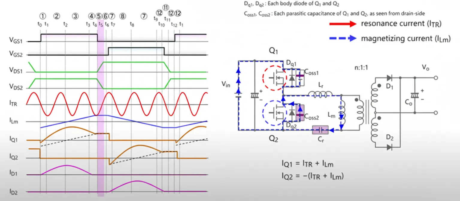
T4–T5: Q1 Off, Dead Time Begins
When Q1 turns off, the magnetizing current charges COSS1 and discharges COSS2. The goal during this interval is to discharge COSS2 to zero to create the condition for Q2 ZVS.
T5–T6: Body Diode Conduction and ZVS Preparation
During T5–T6 the magnetizing current flows through Q2 body diode. ZVS for Q2 is achieved. The interval T4–T6 corresponds to the dead-time period: initially the magnetizing current discharges the capacitances, then it flows through Q2 body diode, creating the conditions necessary for Q2 ZVS.
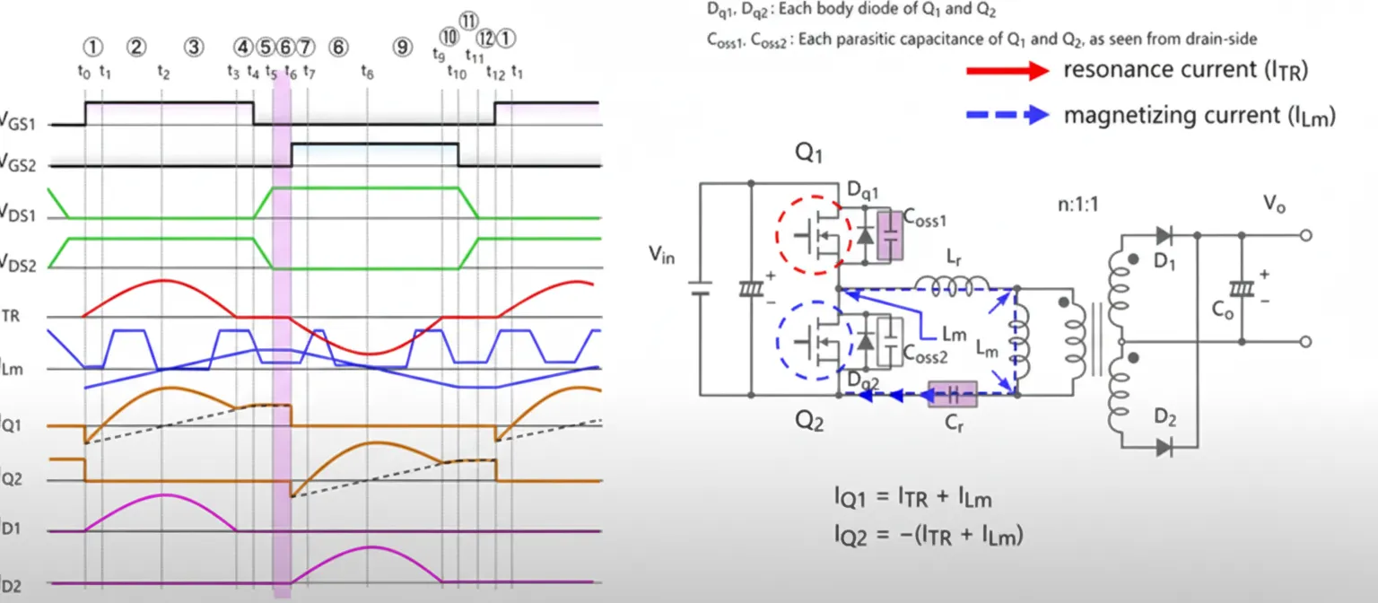
T6–T7: Q2 On
When Q2 turns on, CR and LR resonate. CR discharges into LR, and energy is transferred through D2 to C0. LM is influenced by C0. The resonant current gradually decreases. The resonant current direction is opposite compared with the previous half-cycle, while the magnetizing current remains positive but decreasing. The two currents are not centered together: one component grows while the other shrinks.
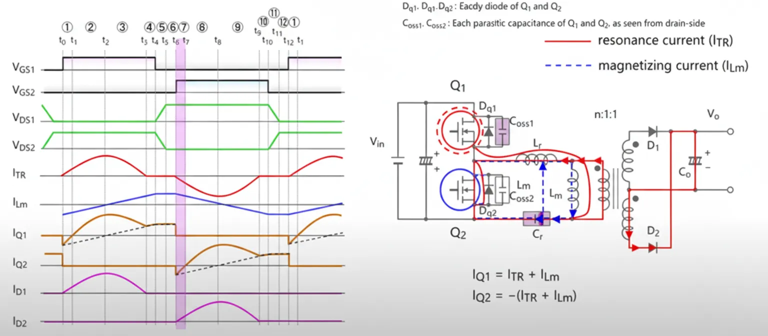
T7–T8
During T7–T8 the magnetizing current is driven toward zero while the resonant current reaches its maximum in the reversed direction.
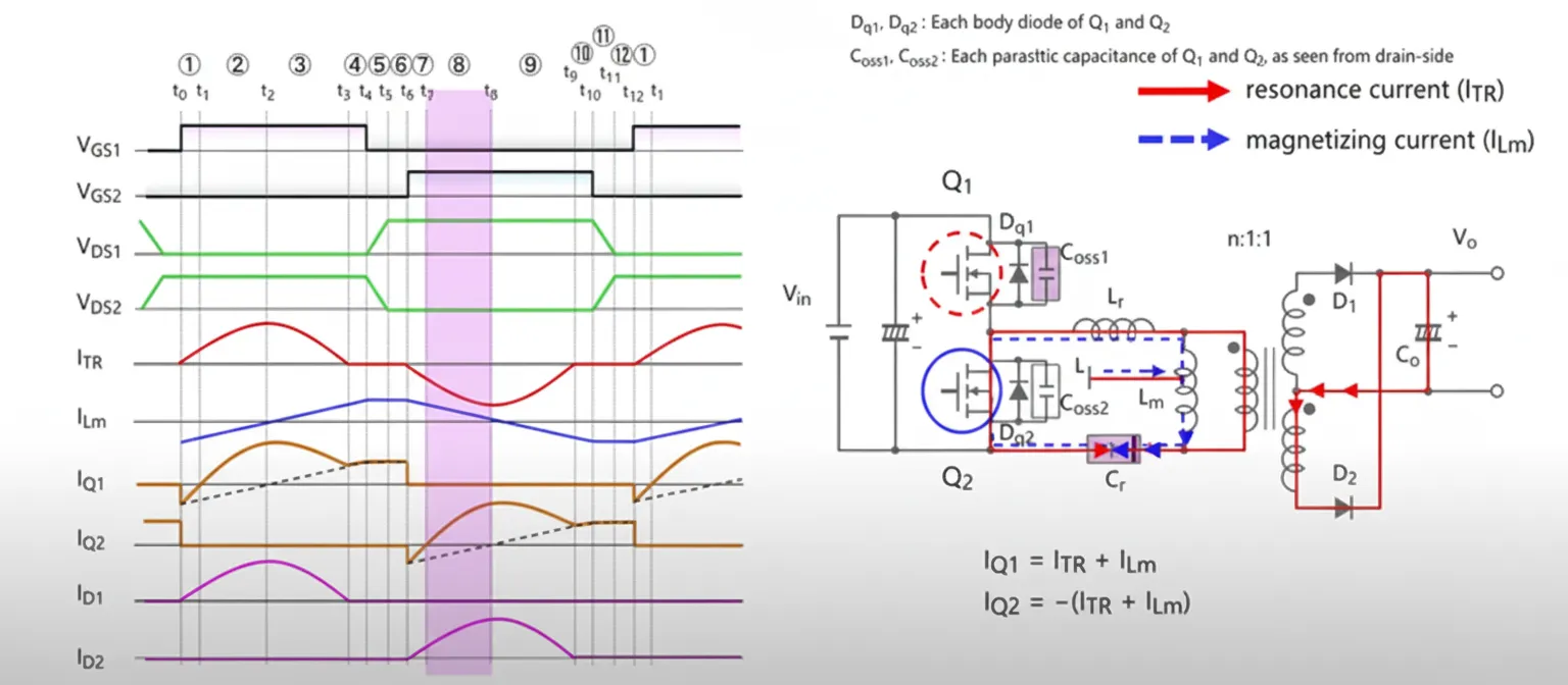
T8–T9
From T8 to T9 the magnetizing current becomes negative and increases in magnitude, while the resonant current decreases. Both currents are negative in this interval; one increases while the other decreases until they meet.
T9–T10
Once the magnetizing current and resonant current are equal, energy transfer through D2 ceases. The circuit then resonates among LM, CR, and LR. Because LM is large, the resonant current can be treated as nearly constant. In effect the resonant component is small and the magnetizing current circulates through Q2.
T10–T11: Q2 Off
When Q2 turns off, the magnetizing current charges COSS2 and discharges COSS1 until COSS1 is driven to zero.
T11–T12: Body Diode Conduction and ZVS for Q1
During T11–T12 the magnetizing current flows through Q1 body diode, creating the condition for Q1 ZVS at the next turn-on.
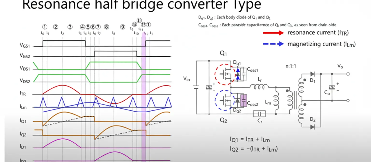
Summary
These 12 states repeat cyclically and constitute the energy exchange in an LLC converter. At times the resonant and magnetizing currents are in phase; at other times they are out of phase. The sequence ensures alternating energy transfer between the primary and the resonant tank, enabling soft switching and efficient operation.