Overview of EV DC Charging Systems
DC fast charging has become the dominant solution for rapid electric vehicle (EV) charging, particularly for commercial fleets and high-utilization vehicles where downtime carries significant costs. Off-board DC charging stations convert grid AC power to high-voltage DC directly at the station, bypassing the vehicle's on-board charger for maximum power delivery.
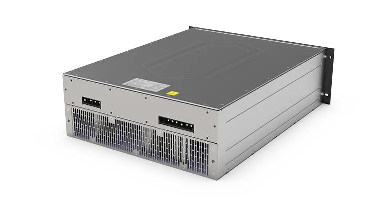
The performance of the AC-DC charging module is the primary determinant of overall station capability. These modules handle rectification, power factor correction, DC voltage regulation, and extensive protection functions in a compact, high-density package.
Market Trends in Power and Voltage Platforms
EV DC chargers have scaled dramatically in power output, evolving from 20 kW to 600 kW+ systems. Modern stations commonly support output voltages from 200 V to 1000 V and currents up to 600 A or higher to accommodate 800 V vehicle platforms and ultra-fast charging.
This evolution demands advanced power electronics capable of wide output ranges, high efficiency, and robust thermal performance under continuous high-load operation.
Charging Module Working Principle
A typical EV DC charging module integrates several key subsystems:
- Three-Phase Active PFC Front-End: Performs rectification, EMI filtering, and power factor correction (typically achieving THDi < 5% and PF ≥ 0.99). Controlled by a dedicated DSP, it shapes input current to align with voltage waveforms.
- DC/DC Converter Stage: Usually a three-level full-bridge topology with high-frequency transformer isolation. This stage regulates the DC bus voltage to the precise output required by the vehicle.
- Auxiliary Power Supplies: Generate low-voltage rails for control circuits from the PFC DC bus.
- Control and Monitoring: DSP-based control with comprehensive input/output sensing for voltage, current, and temperature.
- Communication: CAN bus interface for coordination with the station controller and direct interaction with the vehicle Battery Management System (BMS).
The modular design allows parallel operation of multiple modules to achieve higher total power while enabling current sharing and redundancy.
DC Charging Station System Architecture
A complete DC fast charger typically includes:
- Multiple parallel charging modules
- Master controller
- Insulation monitoring
- Smart metering and billing
- Communication gateways (Ethernet, 4G/5G)
- Contactors, switches, and safety interlocks
- Liquid + air cooling systems
High-power examples (e.g., 480 kW liquid-cooled) support 200-1000 V output at up to 600 A, with peak efficiencies ≥ 95% and full compliance with GB/T standards.
Protection and Safety Functions
Safety is paramount in high-power EV charging. Key protections include:
- Input: Over/under voltage, phase loss, imbalance
- Output: Over/under voltage, overcurrent, short circuit, reverse polarity, backfeed
- Thermal: Overtemperature derating and shutdown for modules, cables, and connectors
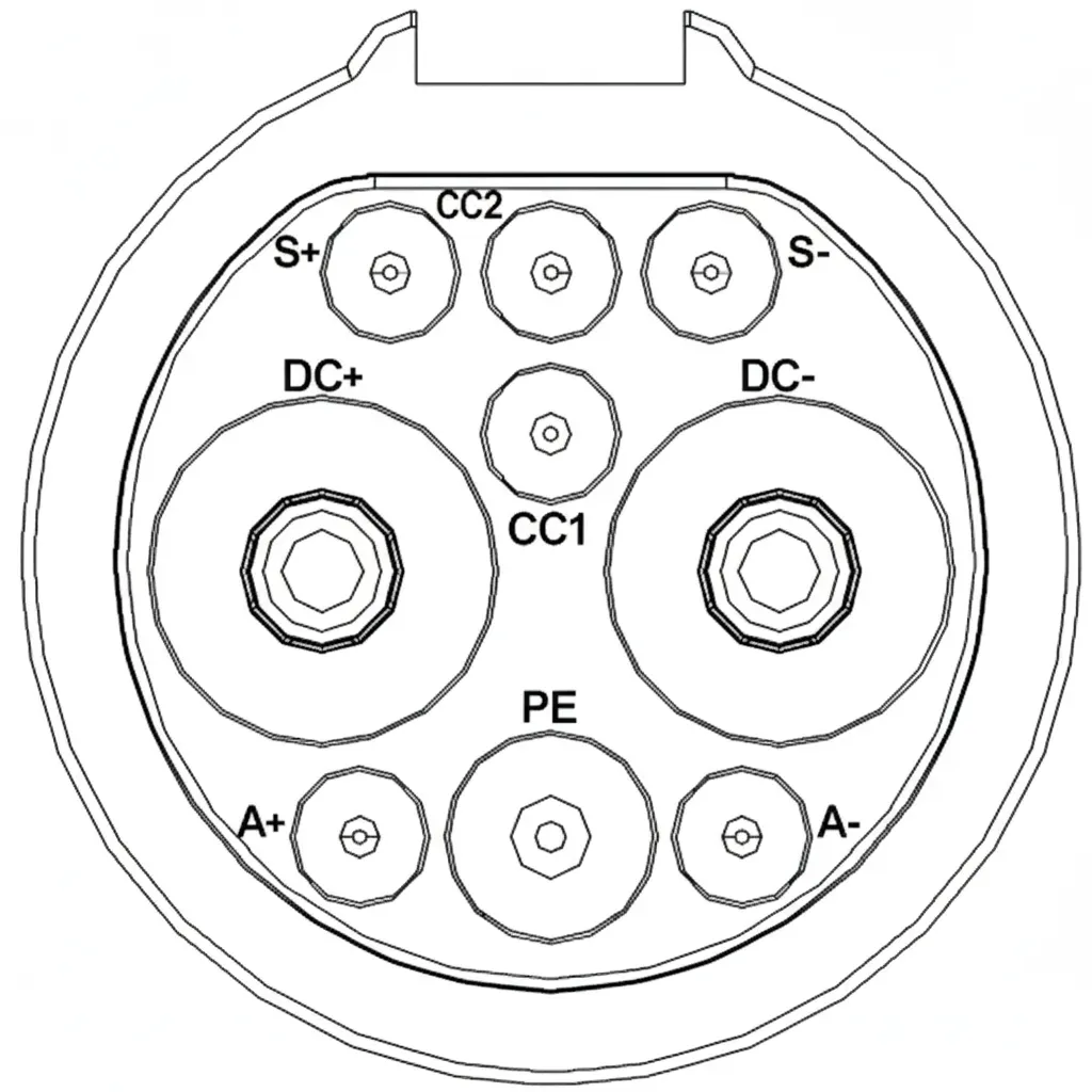
- Insulation monitoring and fault detection
- Contactor status monitoring and emergency shutdown (output voltage < 60 V within 1 s)
- Door interlocks, gun lock, and connection confirmation
These functions rely on precise sensing, fast-acting contactors, and robust firmware.
High-Power Charging Challenges and Thermal Management
High-current operation (hundreds of amps) makes thermal management the most critical engineering challenge. Power dissipation follows P = I^2R, so scaling current dramatically increases heat generation. Effective solutions combine liquid cooling for power modules, optimized busbar design, and advanced thermal interface materials.
PCB Design and Manufacturing Considerations for EV Charging Modules
High-power DC charging modules place extreme demands on PCB technology:
- High-Current Layouts: Heavy copper (4-10 oz or thicker), wide traces, and integrated busbars to minimize resistance and heat.
- Thermal Solutions: Thermal vias arrays, copper pours, and Insulated Metal Substrate (IMS) or metal core PCBs for efficient heat dissipation from power semiconductors.
- High-Voltage Isolation: Creepage and clearance optimization, reinforced insulation, and careful component placement for 1000 V+ operation.
- Power Integrity and EMI Control: Multilayer stackups with dedicated power/ground planes, controlled impedance, and strategic decoupling to support high-frequency switching and low THDi.
- Reliability Engineering: Vibration-resistant designs, conformal coating, and rigorous testing for automotive-grade environmental conditions (-25C to 50C+).
- Modular Assembly: Support for parallel module integration, high-current connectors, and automated production processes.
Electronics manufacturers specializing in new energy power systems deliver the precision PCB fabrication, heavy copper processing, and reliable PCB assembly required for safe, efficient, and scalable EV charging infrastructure.
Industry Outlook
As EV adoption accelerates and charging power continues to rise, charging modules will demand ever-higher power density, efficiency, and intelligence. Success depends on close collaboration between power electronics designers and experienced PCB manufacturing partners capable of delivering robust, high-current solutions.
FAQ
Q1: What is the role of the active PFC in EV charging modules?
A1: It corrects power factor, reduces harmonics (THDi < 5%), and provides a stable DC bus for the downstream converter while meeting EMC standards.
Q2: Why is thermal management critical in high-power DC chargers?
A2: High currents cause significant I^2R losses; effective cooling and PCB thermal design prevent overheating and ensure long-term reliability.
Q3: How do PCBs support EV DC charging systems?
A3: Through heavy copper layouts, advanced thermal management, high-voltage isolation, and high-reliability manufacturing that handle extreme power and environmental requirements.