Overview
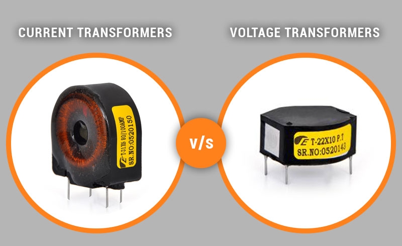
Instrument transformers are used in many electrical systems to measure current, voltage, and power, and to provide protection. They play an important role in power systems. Instrument transformers are classified as current transformers (CTs) and voltage transformers (VTs). Both operate on the principle of converting electrical energy to magnetic energy and back to electrical energy, using electromagnetic induction.
Current Transformers: simplifying high-current measurement
In large electrical systems that form a national or industrial Power Supply—such as in generation, transmission, distribution, and similar environments—currents are often very large and can vary widely, making direct measurement impractical and hazardous. Current transformers are used to convert large primary currents into smaller, proportional secondary currents that are safer and easier to measure, while also providing electrical isolation.
A typical CT consists of an iron core and windings. It has a primary winding and a secondary winding. When an AC source flows through the primary winding, it produces a changing magnetic flux that induces an AC voltage and current in the secondary winding. The primary winding is connected in series with the circuit being measured, and the secondary winding is connected to meters or protective devices. The rated current ratio of a CT depends on the turn counts of the two windings; selecting the correct ratio is essential for proper application. Exceeding the rated current ratio or allowing sustained overloads can damage the transformer.
To achieve low magnetizing ampere-turns, CT core materials are continually improved for lower loss and lower magnetic reluctance. In situations with high current and high voltage where direct use of an ammeter is impossible, CTs enable safe measurement by providing a scaled-down secondary current. Beyond measurement, CTs are widely used for protection: paired with relay devices, a CT detects abnormal current changes such as short circuits or overloads and provides signals to trip the protection device, isolating the faulted circuit. Protection CTs prioritize reliability and stability, requiring adequate accuracy limits as well as thermal and mechanical stability. Electronic current transformers are also common; they offer high stability, reduced saturation, and good linearity, and both electromagnetic and electronic CTs have distinct application advantages.
Voltage Transformers: scaling down high voltages
Voltage transformers also operate on electromagnetic induction, but they transform voltage rather than current. They are similar to conventional transformers but differ in function and are typically lower in capacity. VTs also have two windings, but the winding arrangement contrasts with CTs: the primary winding has more turns and is connected in parallel with the line, while the secondary winding has fewer turns and is connected in parallel with meters and relay devices.
Voltage transformers scale high line voltages down proportionally to levels suitable for measurement and protection, protecting measuring instruments and protective devices from high-voltage stress. VTs are used together with protective relays to monitor abnormal voltage conditions and trigger protective functions. Common VT types include electromagnetic VTs and capacitive voltage transformers (CVTs), where capacitors are used for voltage division before induction to the transformer. CVTs help control voltage division and system harmonic levels. Electronic and optical VTs, which have simpler structures, are increasingly used in digital and automated systems.
Related Reading: Current Transformers vs Voltage Transformers: Key Differences
Summary
Current transformers and voltage transformers share similar electromagnetic principles but differ in function and connection. Both are essential for measurement, control, and protection in electrical systems. Proper selection and application of instrument transformers simplify voltage and current measurement and contribute to system safety and reliability.