Current transformers (CTs) and voltage transformers (VTs), also known as potential transformers (PTs), are critical components in power monitoring, protection, and metering applications. While both are instrument transformers, they serve fundamentally different electrical functions and present distinct challenges for electronics engineers and PCB designers. Understanding these differences is essential for engineers specifying components for smart grid systems, industrial automation, renewable energy inverters, and high-reliability power electronics.
Operating Principles and Basic Functions
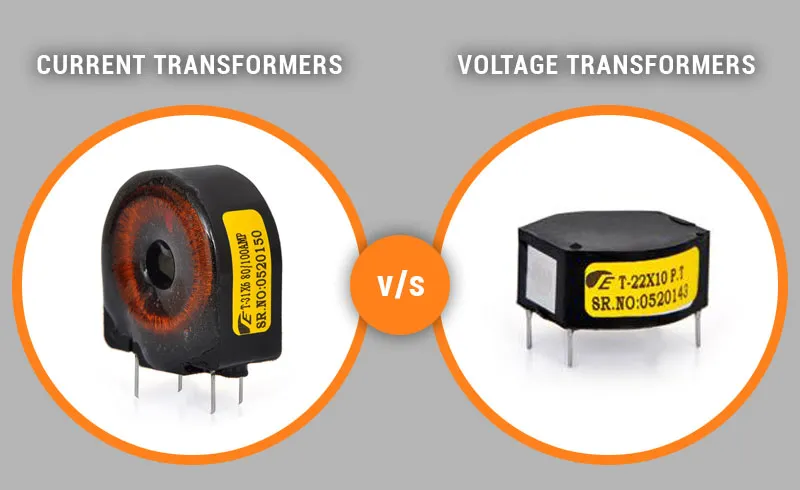
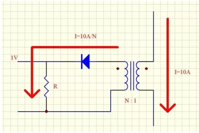
Current Transformers (CTs) reduce high primary currents to manageable secondary levels (typically 1A or 5A) for measurement and protective relays. They operate on the principle that the primary winding is usually a single-turn conductor (the power line itself) passing through a toroidal or split-core magnetic circuit. The secondary winding produces a current proportional to the primary current.
Voltage Transformers (VTs/PTs) step down high voltages to standardized low voltages (typically 100V or 110V) for metering and protection. They function as conventional step-down transformers with both primary and secondary wound on a common magnetic core, maintaining a precise voltage ratio across their operating range.
The core distinction lies in their electrical behavior: CTs are current-driven devices designed to operate near short-circuit conditions on the secondary, while VTs are voltage-driven devices designed to operate near open-circuit conditions on the secondary.
Key Technical Differences
Accuracy and Burden Requirements
CTs are defined by accuracy classes (e.g., 0.1, 0.2, 0.5, 1.0) and burden ratings in VA. A critical parameter is the accuracy limit factor (ALF), which indicates how accurately the CT performs during fault currents. Saturation characteristics must be carefully managed to prevent protection relay malfunctions.
VTs are rated by accuracy classes and burden as well, but their performance is evaluated under varying voltage conditions. The voltage factor (VF) defines the maximum continuous voltage the transformer can withstand without exceeding accuracy limits.
Construction and Magnetic Design
CTs typically use high-permeability silicon steel or nanocrystalline cores to achieve low magnetizing current. The design must minimize phase angle error while preventing saturation under fault conditions. Rogowski coils offer an alternative air-core solution for high-frequency or wide-bandwidth applications.
VTs require low-loss cores with excellent linearity. They often incorporate compensation windings or shielding techniques to reduce ratio and phase errors across the specified voltage range.
Safety Considerations
A secondary circuit of a CT must never be open-circuited while primary current is flowing. Dangerous high voltages can develop across the secondary terminals. Conversely, VTs should not be short-circuited on the secondary, as this creates a near short-circuit condition on the primary.
PCB Design and Electronics Integration Challenges
Miniaturization and High-Frequency Performance
As power electronics move toward higher switching frequencies (SiC and GaN-based systems), traditional 50/60Hz instrument transformers often reach their limitations. PCB designers must consider planar transformers, integrated current sensors (Hall-effect, fluxgate, or shunt-based), and Rogowski coil implementations directly on the board.
Material Selection for Magnetic Components
Core material choice significantly impacts performance. Nanocrystalline and amorphous alloys offer superior frequency response and lower core losses compared to traditional silicon steel, but present unique challenges in automated assembly and mechanical stress sensitivity.
Thermal Management
Both CTs and VTs generate heat due to core losses and copper losses. In dense PCB layouts, thermal modeling becomes critical, particularly when sensors are placed near high-current traces or power semiconductors.
Isolation and Creepage Requirements
High-voltage applications demand careful attention to insulation systems, creepage distances, and clearance requirements per IEC 60664 and UL standards. This directly influences layer stack-up design, material selection (FR-4, high-CTI laminates, or polyimide), and conformal coating specifications.
Manufacturing Considerations for Precision Transformers
Producing reliable current and voltage transformers at scale requires tight process control:
- Consistent winding tension and precise turn counts.
- Controlled core annealing processes.
- Vacuum impregnation or potting to eliminate air gaps.
- Automated testing for ratio, phase angle, and burden performance.
- Traceability systems for magnetic materials.
For PCB-mounted solutions, solderability, coplanarity, and reflow temperature compatibility become critical parameters that must be balanced with electrical performance.
Industry Applications and Selection Criteria
Current Transformers are preferred for:
- Power quality monitoring.
- Motor protection relays.
- Energy metering in industrial settings.
- Renewable energy inverters.
- Battery management systems.
Voltage Transformers are essential for:
- Voltage measurement in medium-voltage switchgear.
- Grid synchronization of inverters.
- Capacitor bank control.
- Power factor correction systems.
Engineers must evaluate frequency response, linearity, isolation voltage, temperature stability, and regulatory compliance when selecting between technologies.
The Role of Advanced PCB and Flexible Circuit Technologies
Modern electronic systems increasingly integrate current and voltage sensing directly into the PCB or flexible circuit assembly. This integration demands expertise in:
- High-density interconnect (HDI) design for precision analog sections.
- Controlled impedance routing for signal integrity.
- Mixed-signal layout practices separating high-current paths from sensitive measurement circuitry.
- Advanced materials with stable dielectric constants for consistent sensor performance.
- Flexible circuit solutions for space-constrained or mechanically dynamic applications.
Successful implementation requires close collaboration between transformer designers, PCB fabricators, and system engineers to balance electrical performance, manufacturability, and long-term reliability.
Conclusion
While current transformers and voltage transformers share the name "transformer," their operating principles, design constraints, and integration challenges differ significantly. As power electronics grow more sophisticated and compact, the boundary between traditional instrument transformers and PCB-integrated sensing solutions continues to evolve. Manufacturers and design engineers who understand both the fundamental electrical differences and the practical manufacturing implications are best positioned to develop reliable, high-performance power systems for tomorrow's energy infrastructure.
Optional FAQ Section
Q1: Can current transformers and voltage transformers be used together in the same system?
A1: Yes. In most power monitoring and protection systems, CTs and VTs are used together to provide complete current, voltage, and power measurements.
Q2: What is the main advantage of PCB-integrated current sensors over traditional CTs?
A2: PCB-integrated solutions offer smaller size, lower weight, wider bandwidth, and elimination of secondary wiring errors, though they may have different accuracy and isolation characteristics.
Q3: How do nanocrystalline cores compare to traditional silicon steel in instrument transformers?
A3: Nanocrystalline materials typically provide higher permeability, lower core losses, better high-frequency performance, and reduced size, but often come at higher material cost and require more careful handling during manufacturing.