Overview
More applications require fast, accurate current monitoring, including autonomous driving, factory automation and robotics, communication systems, server power management, D-class audio amplifiers and medical systems. Many of these applications need bidirectional current measurement implemented with minimal cost.
Although a bidirectional current-sense amplifier (CSA) can be built from two unidirectional CSAs, that approach can be complex and time consuming. It may require combining two outputs into a single-ended output with an independent rail-to-rail operational amplifier, or using two ADC inputs on a microcontroller, which adds firmware and machine-cycle overhead. Using two unidirectional CSAs plus the extra components needed to integrate them into a bidirectional solution increases PCB area, reduces reliability, and increases inventory. That can raise cost and delay schedules.
To avoid these issues, designers can choose integrated, high-speed, precision bidirectional CSAs. The most compact option uses an integrated bidirectional CSA with an internal low-inductance shunt resistor; alternatively, CSAs that use external shunts provide greater layout flexibility.
Using Two Unidirectional CSAs
Bidirectional CSA circuits can be constructed from two unidirectional CSAs in several ways. In the left example in Figure 1, the Analog Devices MAX4172ESA+T has no internal load resistor, so discrete resistors Ra and Rb are used. In the right example, the MAX4173TEUT+T integrates a 12 kΩ load resistor to convert its current output to a voltage.
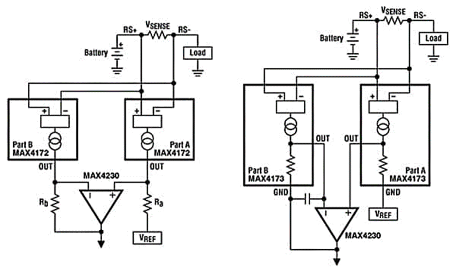
Although only one load resistor is required in some cases, the MAX4173TEUT+T circuit adds a 1 nF capacitor in the feedback of the B section to stabilize that control loop. In both examples, a general-purpose amplifier such as the MAX4230AXK+T combines the output currents from the two CSAs.
Both approaches use more components than a single integrated bidirectional CSA. Besides the increased part count, placing two unidirectional CSAs close to the VSENSE resistor complicates PCB layout.
Example Applications for Bidirectional CSAs
Bidirectional CSAs are versatile and appear in many applications. For example, in a three-phase servo motor system, two CSAs can be used to determine instantaneous winding currents for all three phases without additional calculations or any information about PWM pulse phase or duty cycle (Figure 2).
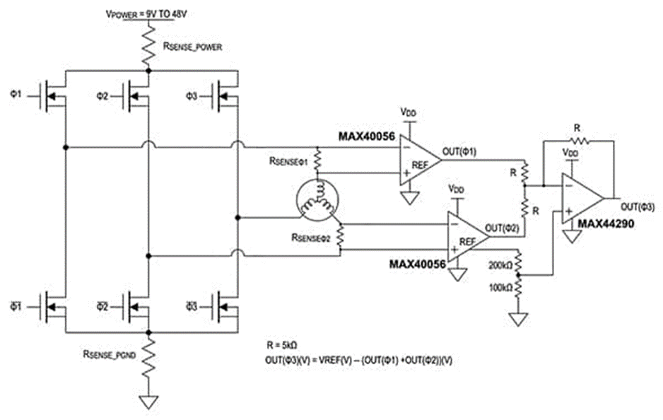
By Kirchhoff's law, the sum of the currents in the first two windings equals the third winding current. The circuit in Figure 2 uses two MAX40056TAUA+ bidirectional CSAs to measure two phase currents and a MAX44290ANT+T general-purpose op amp to sum the currents. Because all three amplifiers share the same reference voltage, the result is a ratiometric measurement.
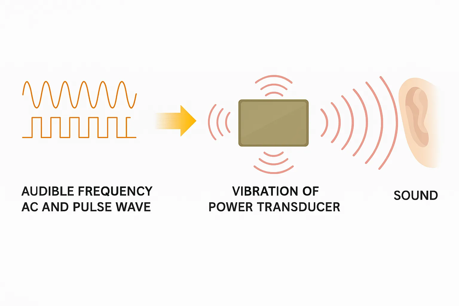
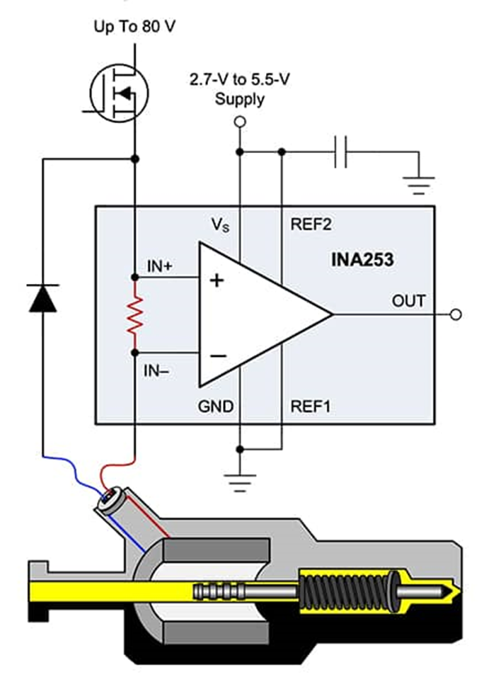
In another example, a D-class audio amplifier can use a bidirectional CSA such as the Texas Instruments INA253A1IPW to accurately measure a speaker's load current (Figure 3).
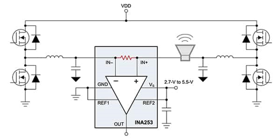
Real-time measurement of speaker load current supports diagnostics and amplifier optimization by quantifying key speaker parameters and their variation, including coil resistance, speaker impedance, resonance frequency and peak impedance at resonance, and the speaker's instantaneous ambient temperature.
PCB Layout Tips and Shunt Considerations
Parasitic resistance and inductance are important considerations when implementing current-sensing circuits. Excessive soldering and parasitic resistance cause measurement errors. Four-terminal current-sense resistors are commonly used. If four-terminal parts are not available, use Kelvin PCB layout techniques as shown in Figure 4.
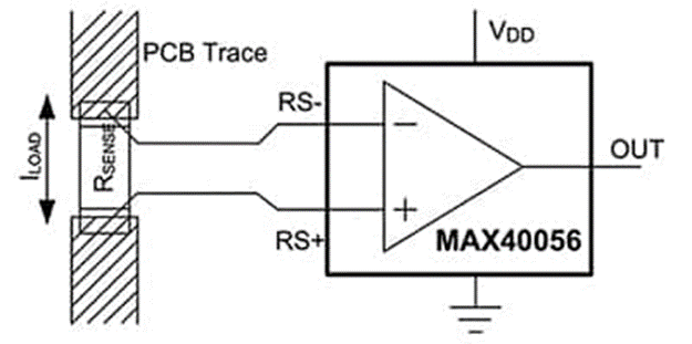
Place Kelvin sense traces as close as possible to the shunt resistor solder pads to minimize parasitic resistance. Larger spacing in the Kelvin sense traces increases measurement error due to the additional trace resistance.
Selecting the right shunt resistor is important to minimize parasitic inductance. Because voltage error is proportional to load current, minimize package inductance. Wirewound resistors have the highest inductance, standard metal-film parts have moderate inductance, and low-inductance metal-film resistors are generally recommended for current sensing.
The shunt value balances dynamic range and power dissipation. For large currents, low-value shunts minimize heat dissipation (I2R). For low currents, larger shunt values reduce the impact of offset voltages on the measurement.
Most CSAs use external shunts, though some include internal shunts. Internal-shunt designs are more compact with fewer parts but trade off flexibility because the shunt value is fixed, require higher quiescent current than some external-shunt solutions, and limit the measurable current range based on the internal shunt specification.
High-Voltage Precision Bidirectional CSA
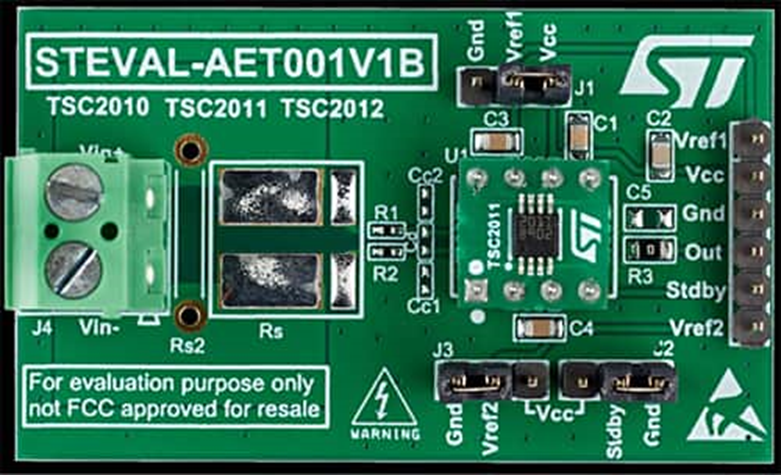
Using STMicroelectronics' TSC2011IST, designers can take advantage of its precision characteristics to use a low-value external shunt and minimize power dissipation (Figure 5). This bidirectional CSA targets accurate current measurement for data acquisition, motor control, solenoid control, instrumentation, test and measurement, and process control.
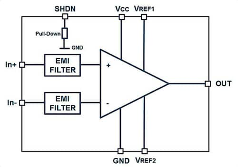
The TSC2011IST amplifier has a gain of 60 V/V, integrated EMI filtering, and 2 kV HBM ESD tolerance per JEDEC JESD22-A114F. It can detect full-scale voltage drops down to 10 mV for stable measurements. With a 750 kHz gain-bandwidth product and 7.0 V/μs slew rate, it delivers high accuracy and fast response.
Designers can evaluate the TSC2011IST with the STEVAL-AETKT1V2 evaluation board (Figure 6). The device can sense current over a wide common-mode range from -20 V to +70 V. Key specifications for the TSC2011IST include:
- Gain error: max 0.3%
- Offset drift: max 5 μV/°C
- Gain drift: max 10 ppm/°C
- Quiescent current: 20 μA in shutdown
Integrated Bidirectional Shunt CSA
Texas Instruments' INA253A1IPW integrates a 2 mΩ, 0.1% low-inductance shunt and supports up to 80 V common-mode voltage (Figure 7). The INA253A1IPW provides enhanced PWM suppression for designs exposed to large dv/dt, enabling continuous, real-time current measurement in motor drive and solenoid control applications. The internal amplifier uses a precision zero-drift topology with DC common-mode rejection ratio (CMRR) greater than 120 dB and 90 dB AC CMRR at 50 kHz.
Designers can accelerate system development with the INA253EVM evaluation board, which exposes INA253A1IPW pins via test points (Figure 8). The two-layer board measures 2.4 × 4.2 in and uses 1 oz copper.
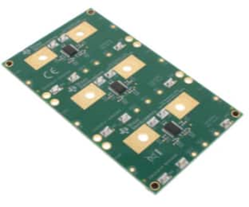
The PCB includes minimal supporting circuitry and can be reconfigured, removed, or bypassed as needed. INA253EVM features:
- Three INA253A1IPW devices
- All pins easily accessible
- PCB layout and structure that supports ±15 A through the INA253 CSAs across -40 to +85°C
- Sockets on the PCB to allow alternative configurations beyond the default
- A bottom layer that is a solid copper plane to provide a low-impedance return path
AEC-Q100 Qualified Bidirectional CSA
For current monitoring in full-bridge motor control, switching power supplies, solenoids, battery packs, and automotive applications, designers can use Analog Devices' LT1999IMS8-20#TRPBF (Figure 9).
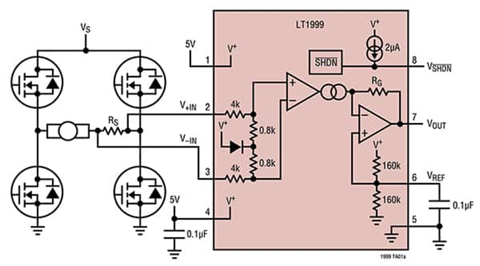
The LT1999IMS8-20#TRPBF meets AEC-Q100 requirements for automotive applications and includes a shutdown mode to minimize power consumption. It measures current with an external shunt and generates a proportional output voltage referenced to a midscale reference node between supply and ground. Designers may use an external voltage to set the reference level.
If VSHDN (pin 8) is driven to 0.5 V above ground, the LT1999 enters a low-power shutdown state with about 3 μA current consumption. If the input pins (+IN and -IN) are biased within 0 to 80 V (with no differential voltage applied), input leakage is about 1 nA. An internal first-order differential low-pass EMI suppression filter reduces EMI sensitivity and helps reject high-frequency signals outside the device bandwidth.
Analog Devices provides the DC1698A demonstration board for LT1999 series evaluation. The board amplifies the voltage drop across the onboard current-sense resistor and produces a bidirectional output voltage proportional to current through the resistor. Designers can choose fixed gains of 10 V/V (DC1698A-A), 20 V/V (DC1698A-B), or 50 V/V (DC1698A-C).
PWM Suppression Capable Bidirectional CSA
To improve suppression of common-mode PWM edges in designs that drive inductive loads such as solenoids and motors, designers can use the MAX40056TAUA+ (Figure 10). As noted earlier, the MAX40056TAUA+ is a bidirectional CSA that can handle slew rates of ±500 V/μs and higher. Typical CMRR is 60 dB at 50 V with ±500 V/μs input and 140 dB DC. The common-mode range is -0.1 V to +65 V, and the device provides protection for inductive flyback voltages down to -5 V.
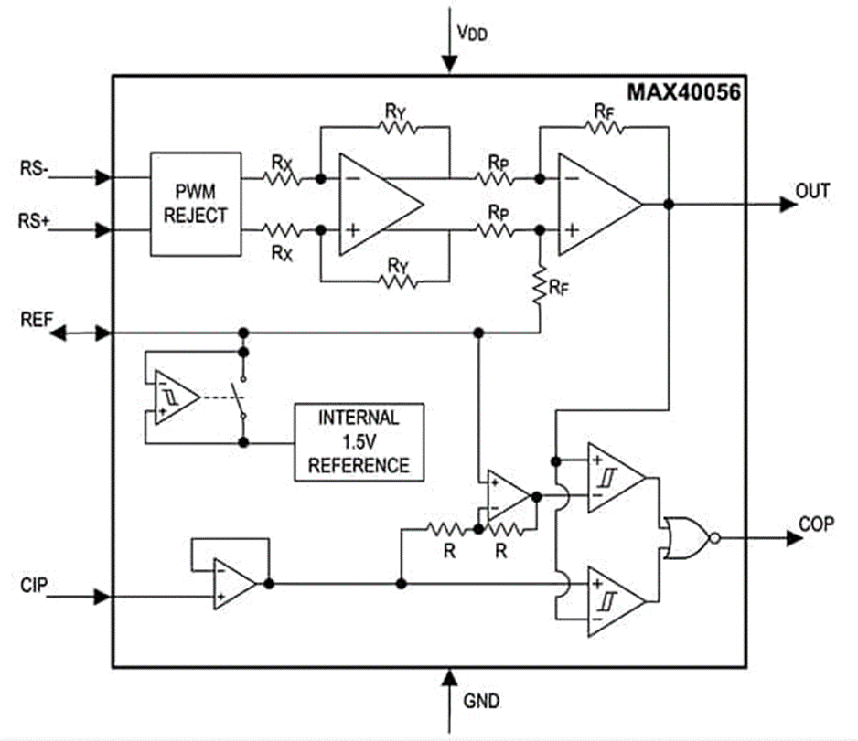
The MAX40056TAUA+ includes an internal 1.5 V reference that can be used to:
- Drive a differential ADC
- Offset the output to indicate current direction
- Source current into an external load to mitigate performance degradation
When a higher full-scale output swing is useful or when supply voltage exceeds 3.3 V, designers can override the internal reference with a higher external reference. The internal or external reference can also set thresholds for the integrated overcurrent comparator to provide immediate overcurrent fault signals.
The MAX40056EVKIT# evaluation kit provides a platform for developing high-precision, high-voltage bidirectional CSA applications such as solenoid drivers and servo motor controllers.
Conclusion
A wide range of applications require fast, accurate current monitoring, from autonomous vehicles, factory automation and robotics to communication systems, server power management, D-class audio amplifiers and medical equipment. In many cases, bidirectional current sensing is required.
Designers can choose from a variety of integrated bidirectional CSAs and associated development platforms to implement fast, accurate bidirectional current monitoring efficiently.