Introduction
As switching power supplies are integrated into a wide range of equipment, engineers evaluate control structures to optimize performance. There is no single control topology that is universally best; the optimal choice depends on the specific application. The following compares voltage-mode and current-mode controls, outlining their strengths and weaknesses.
Voltage-Mode Control
Voltage-mode control was used in early switching regulator designs and has continued to meet many power-supply requirements. The basic voltage-mode control topology is shown below.
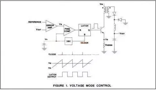
In this mode there is a single voltage feedback path. Pulse-width modulation is achieved by comparing the voltage-error signal with a fixed ramp (sawtooth) waveform. Current limiting must be implemented with external circuitry.
For fixed-frequency PWM, the switching frequency remains constant while the pulse width (duty cycle) varies. The voltage reference (VR) is fixed. In current-mode control, the sensed current can serve as a reference. In steady state, volt-second balance applies: VIN * TON = VOUT * TOFF, so the supply is stable in steady state.
Advantages of Voltage-Mode
- Single feedback loop makes design and analysis simpler.
- A large-amplitude ramp provides good noise margin for stable modulation.
- Low output impedance improves cross-regulation for multi-output supplies.
Disadvantages of Voltage-Mode
- Voltage or load changes are detected only at the output and must be corrected via the feedback loop, producing slower transient response.
- The output filter adds two poles to the control loop, requiring the error amplifier to place the dominant pole at low frequency or the compensator to add a zero to cancel the poles.
- Loop gain varies with input voltage, complicating compensation.
Current-Mode Control
The basic current-mode control topology is shown below.
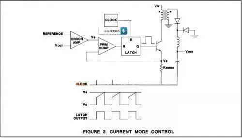
In current-mode control, the oscillator provides a fixed-frequency clock, while the ramp is effectively replaced by a signal derived from the inductor current.
Advantages of Current-Mode
- Because the inductor current rises with a slope proportional to VIN - VOUT, the control responds immediately to input-voltage changes, eliminating delay-related gain variation.
- With the error amplifier controlling current, the inductor has minimal effect on loop dynamics; the output filter contributes only a single pole to the feedback loop, simplifying compensation and allowing higher gain-bandwidth compared with voltage mode.
- Provides inherent cycle-by-cycle current limiting; current limit can be set by clamping the error-amplifier control signal (many controllers clamp around 1 V). This facilitates paralleling supplies and load sharing, and can help with issues such as transformer flux imbalance in push-pull topologies.
Disadvantages of Current-Mode
- Two feedback loops increase analysis complexity.
- Control-loop instability can occur when duty cycle exceeds ~50%; slope compensation is required.
- Resonances in the power stage can inject noise into the control loop because modulation is based on a current-derived signal.
- Current spikes can result from transformer winding capacitance and reverse-recovery currents of secondary rectifiers.
- Load regulation is generally worse because the control loop implements current drive.
- Multi-output designs require coupled inductors to achieve acceptable cross-regulation.
Comparison and Improvements
Current-mode control alleviates many voltage-mode limitations but introduces its own design challenges. Voltage-mode control has also seen improvements, primarily through input-voltage feedforward and higher IC speed.
Input-voltage feedforward adjusts the ramp slope proportional to input voltage, providing corresponding duty-cycle correction without requiring action from the feedback loop. This produces a more constant loop gain and immediate response to input changes.
Higher-speed IC processes such as BiCMOS reduce parasitic capacitance and circuit delay, mitigating several issues previously associated with voltage-mode control.
Selecting a Control Mode
Both voltage-mode and current-mode controls remain viable; the appropriate choice depends on the application.
Consider current-mode when:
- The output is a current source or the output voltage is very high.
- The fastest possible dynamic response is required for a given switching frequency.
- The application is a DC-DC converter with limited input-voltage variation.
- Modular designs require paralleling and load sharing.
- Push-pull circuits where transformer flux balance is critical.
- Cost-sensitive designs that require minimal external components.
Consider voltage-mode with feedforward when:
- The input voltage and/or output load can vary over a wide range.
- At low-voltage, light-load conditions, the current-slope may be too shallow for stable PWM operation.
- High-power or high-noise applications where noise on the current waveform is difficult to manage.
- Multiple output voltages are needed with good cross-regulation.
- An auxiliary saturable reactor controller is used as a secondary-side regulator.
- You want to avoid the complexity of dual feedback loops and slope compensation.
Summary
This article summarized the characteristics and differences between current-mode and voltage-mode control in switching power supplies, and highlighted recent improvements in voltage-mode designs. The discussion should help engineers select the most appropriate control approach for their specific application.